
Radio frequency identification (RFID) solution to lost time spent on instrument inventory

a technology of instrument inventory and frequency identification, applied in the field of radio frequency identification (rfid) tags, can solve the problems of increasing hospital and medical facilities costs, increasing patient risk, and wasting patient time,

Inactive Publication Date: 2007-06-21
SYMBOL TECH INC
View PDF9 Cites 51 Cited by
  • Summary
  • Abstract
  • Description
  • Claims
  • Application Information

AI Technical Summary

Benefits of technology

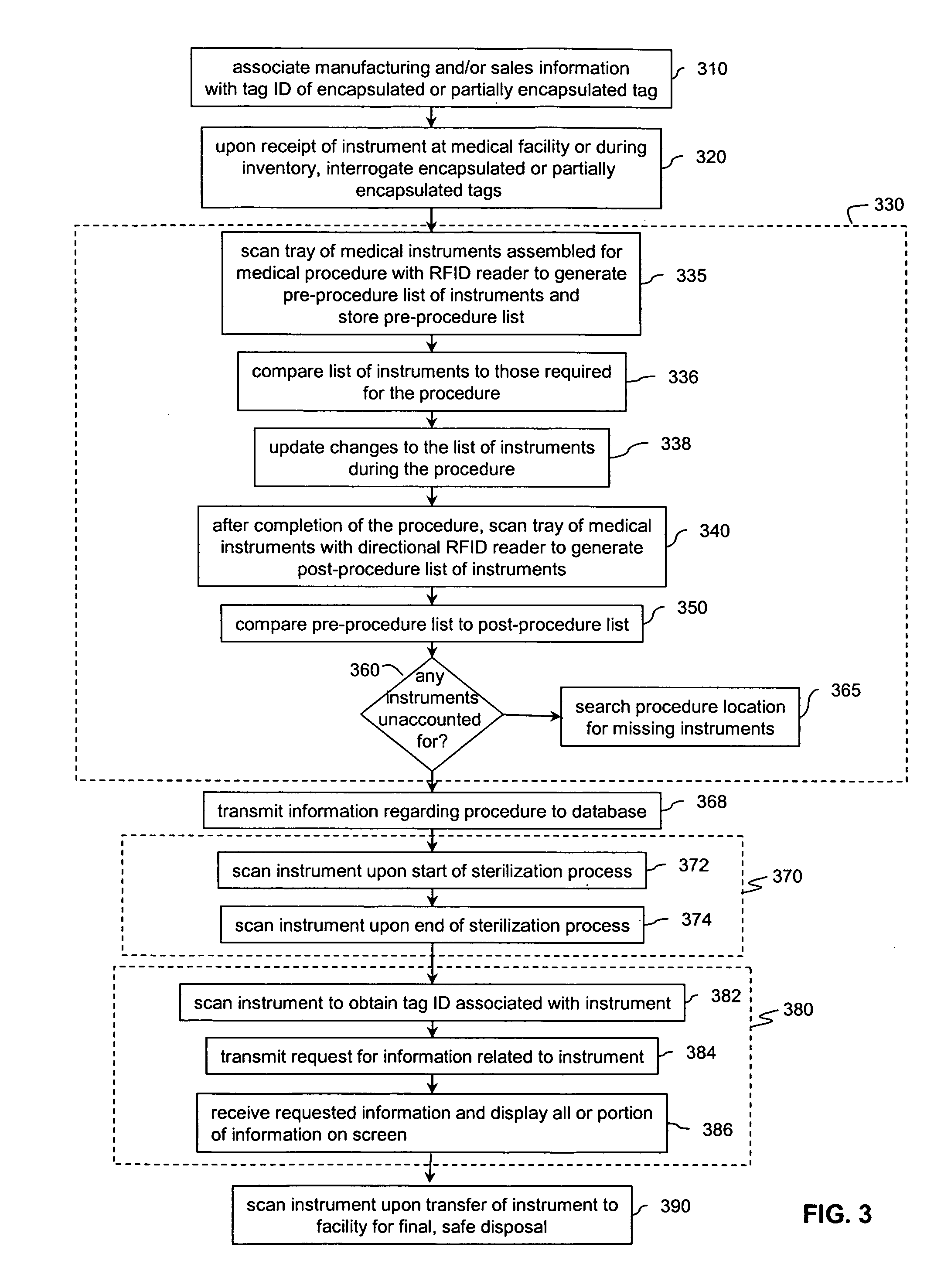
[0008] The present invention is further directed to methods for tracking medical instruments having encapsulated or partially encapsulated RFID tags. In accordance with aspects of the invention, one or more instruments assembled for a medical procedure are scanned to generate a list of pre-procedure RFID tag identification numbers. The pre-procedure list of tag identification numbers is then stored. Upon completion of the procedure, one or more instruments are scanned to generate a list of post-procedure RFID tag identification numbers. The pre-procedure and post-procedure lists of tag identification numbers are compared to identify any missing instruments. If instruments are missing, the location of the medical procedure can be scanned to locate the identified missing instruments.

Problems solved by technology

For example, surgeons, nurses, and other medical personnel spend significant time delaying the end of a procedure in order to account for misplaced medical instruments.
This delay increases costs to hospital and medical facilities (e.g., lost hours of operating theater teams) and increases risk to patients due to extended time under anesthesia.
This process is time consuming and prone to human errors.
In addition, the use of traditional methods of RFID tag attachment to medical instruments is not practical for a variety of reasons.
Furthermore, many current RFID tag structures cannot withstand repeated sterilization processes.

Method used


Image

  • Radio frequency identification (RFID) solution to lost time spent on instrument inventory
  • Radio frequency identification (RFID) solution to lost time spent on instrument inventory
  • Radio frequency identification (RFID) solution to lost time spent on instrument inventory

Examples


Embodiment Construction

1.0 Introduction

[0022] Radio frequency identification (RFID) tags are electronic devices that may be affixed to items whose presence is to be detected and / or monitored. The presence of an RFID tag, and therefore the presence of the item to which the tag is affixed, may be checked and monitored by devices known as “readers.” Readers typically transmit radio frequency signals to which the tags respond. Each tag can store a unique identification number. The tags respond to the reader transmitted read signals by providing their identification number so that they can be identified.

[0023]FIG. 10 illustrates an environment 1000 where one or more RFID tag readers 104 communicate with an exemplary population of RFID tags, according to the present invention. As shown in FIG. 10, the population of tags 1022 includes seven tags 1020a-1020g. According to embodiments of the present invention, a population of tags 1022 may include any number of tags 1020.

[0024] Exemplary environment 1000 also i...


PUM

PropertyMeasurementUnit
temperatureaaaaaaaaaa
timeaaaaaaaaaa
speedaaaaaaaaaa

Abstract

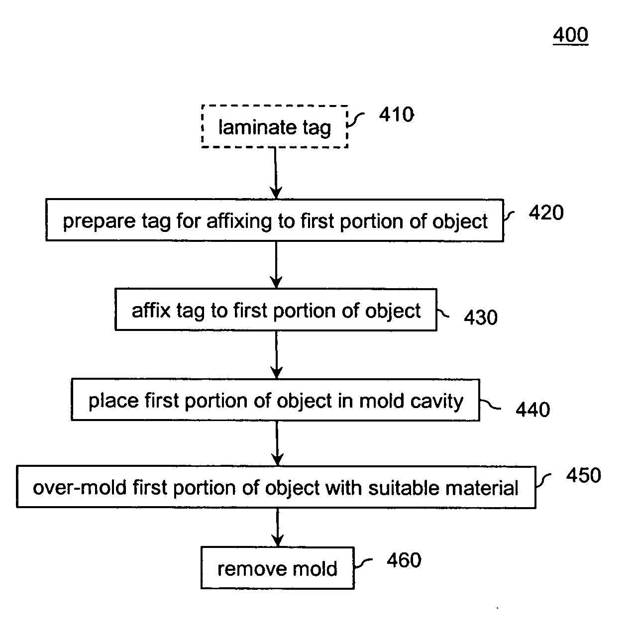
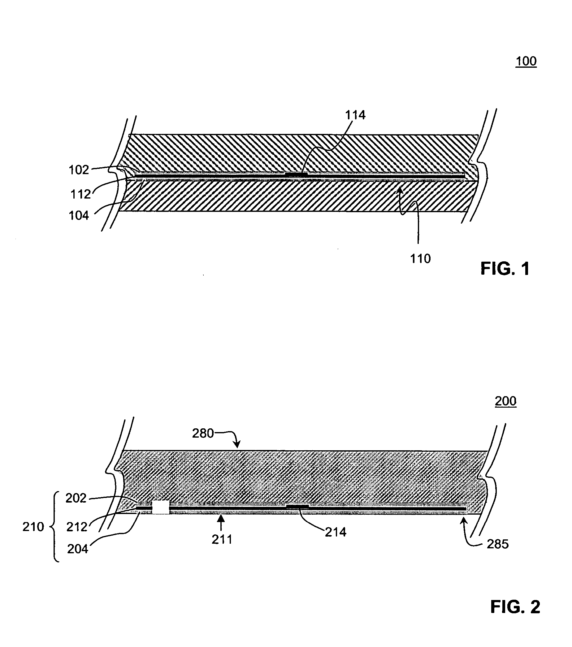
A method for manufacturing an object having an encapsulated radio frequency identification (RFID) tag is provided. An RFID tag is mechanically or chemically affixed to a first portion of the object being manufactured. The first portion of the object, with the RFID tag affixed is placed in a cavity of a mold. The first portion is then over-molded with a first material such as high temperature thermoplastic or low temperature thermoset to generate a seamless object. A method for manufacturing an object having a partially encapsulated RFID tag is also provided. An RFID tag is laminated with a lamination material, such as high temperature thermoplastic. The laminated RFID tag is affixed to a mold. The laminated RFID tag is then over-molded with a first material to generate a seamless object. Methods for tracking medical instruments having encapsulated or partially encapsulated RFID tags are also provided.

Description

FIELD OF THE INVENTION [0001] The present invention is related generally to radio frequency identification (RFID) tags and specifically to RFID tags encapsulated or partially encapsulated within objects using high and low temperature manufacturing methods and the use of those objects in the field of medicine. BACKGROUND OF THE INVENTION [0002] The ability to quickly inventory instruments is critical in certain applications. For example, surgeons, nurses, and other medical personnel spend significant time delaying the end of a procedure in order to account for misplaced medical instruments. This delay increases costs to hospital and medical facilities (e.g., lost hours of operating theater teams) and increases risk to patients due to extended time under anesthesia. Current methods for generating a pre-procedure and post-procedure inventory of medical instruments are manual. For example, an individual makes a list of instruments assembled for use in the procedure. After the procedure,...

Claims


Application Information

Patent Timeline
Patent Type & Authority Applications(United States)
IPC IPC(8): A01J25/13G08B13/14G16H40/40
CPCB29C45/14639B29C45/14647B29C2045/14852B29L2031/753G06Q10/08G06Q50/22G06Q50/28G08B13/2417G08B13/2445G16H40/40
Inventor AUSTIN, TIMOTHY B.
Owner SYMBOL TECH INC
Learn More