
Ink cartridge venting

a technology of ink cartridges and venting pipes, which is applied in the field of inkjet printing, can solve the problems of very problematic gaseous species present in the starter tank, and achieve the effects of reducing the amount of ink, and maintaining the pressure balan

Active Publication Date: 2007-06-21
SLINGSHOT PRINTING LLC
View PDF21 Cites 26 Cited by
  • Summary
  • Abstract
  • Description
  • Claims
  • Application Information

AI Technical Summary

Benefits of technology

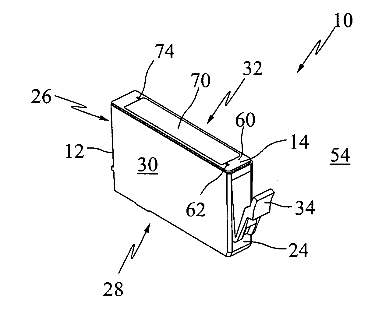
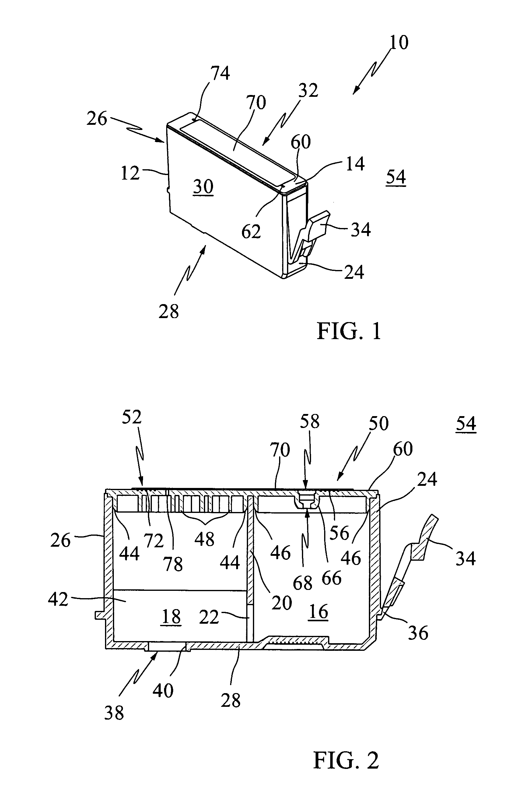
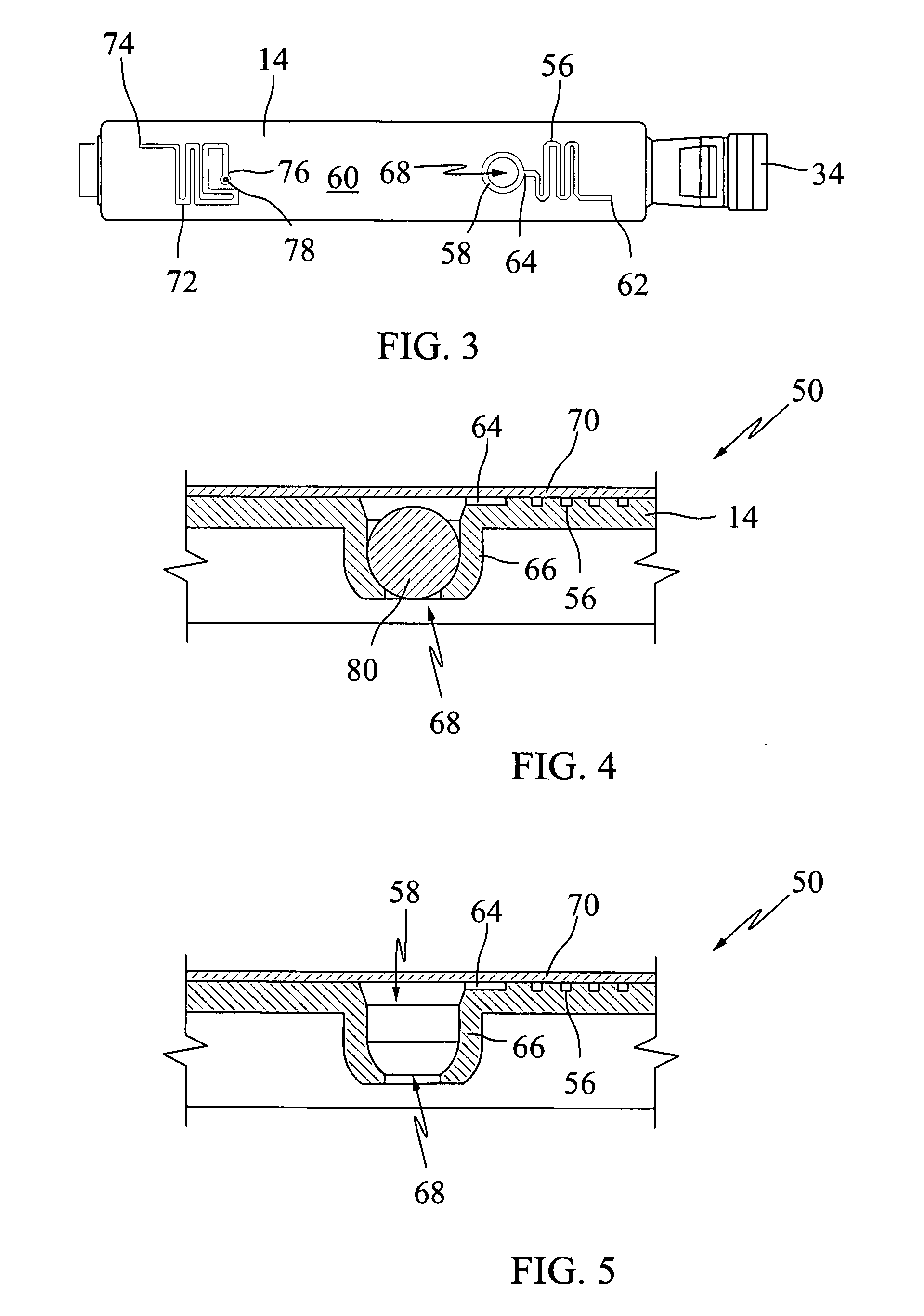
"The present invention relates to an ink tank for inkjet printers that can be used with different types of ink tanks. The invention includes a tank body with multiple chambers for housing ink, including a free ink chamber and a felt chamber. The invention also includes a universal ink tank cap that can accommodate replacement situations where both the free ink chamber and the felt chamber are at least substantially full. The invention solves the problem of gas expansion and contraction in ink tanks during shipping, by providing vents that allow the gas to communicate with an external environment. The invention also includes a tank cap with a felt chamber vent and a free ink chamber vent, as well as a covering that forms a duct for the felt chamber and the external environment. The invention allows for the efficient and cost-effective replacement of ink tanks and the acclimation of users to the printer."

Problems solved by technology

The gaseous species present in starter tanks can be very problematic, especially during shipment.

Method used


Image

  • Ink cartridge venting
  • Ink cartridge venting
  • Ink cartridge venting

Examples


Embodiment Construction

[0025] The exemplary embodiments of the present invention are described and illustrated below to encompass methods and devices resulting from such methods for venting the contents of a disposable ink tank. In addition, the exemplary embodiments utilize interchangeable parts such as interchangeable ink tank lids for starter and replacement ink tanks not before recognized, disclosed, or utilized. Of course, it will be apparent to those of ordinary skill in the art that the preferred embodiments discussed below are exemplary in nature and may be reconfigured without departing from the scope and spirit of the present invention. However, for clarity and precision, the exemplary embodiments as discussed below may include optional steps, methods, and features that one of ordinary skill should recognize as not being a requisite to fall within the scope of the present invention.

[0026] Referencing FIGS. 1 and 2, an exemplary disposable ink tank 10 includes a hollowed out body 12 that receive...


PUM


Abstract

An ink cartridge comprising: (a) an ink cartridge body including a floor and an exterior wall partially defining an interior volume, the ink cartridge body including a capillary producing medium; and (b) an ink cartridge cap mounted to the ink cartridge body to substantially enclose the interior volume, the ink cartridge cap including two vents in direct communication with the interior volume, wherein a first vent incorporates an ink supply port. The invention also includes the utilization of a universal ink tank lid for use both in replacement and starter ink tank configurations, as well as methods of utilizing a universal ink tank lid to reduce production costs and complexities.

Description

FIELD OF THE INVENTION [0001] The present invention is directed to inkjet printing and, more specifically, to methods and devices resulting from such methods for venting inkjet ink cartridges. The present invention makes use of multiple vents for an ink cartridge to allow for the flow of gases into or from the ink cartridge. BACKGROUND AND SUMMARY [0002] The present invention makes use of a universal tank lid fabricated with multiple vents for use in instances when an ink tank is full of ink and when an ink tank is partially filled with ink. More specifically, supply side items such as ink tanks or ink cartridges must be periodically replaced after the inkjet printer deposits a predetermined volume of ink onto a print medium. Ink from these replaceable or refillable cartridges supplies the inkjet nozzles of the printhead so that continued printing is contingent upon a sufficient supply of ink. [0003] Those skilled in the art are well aware that original equipment manufacturers (OEMs...

Claims


Application Information

Patent Timeline
Patent Type & Authority Applications(United States)
IPC IPC(8): B41J2/175
CPCB41J2/17506B41J2/17513
Inventor ANDERSON, JAMES DANIEL JR.GRAY, TREVOR DANIELGREER, DAVID EMERSON
Owner SLINGSHOT PRINTING LLC
Learn More