Microfabricated light collimating screen

Active Publication Date: 2007-06-21
E INK CORPORATION
View PDF9 Cites 93 Cited by
  • Summary
  • Abstract
  • Description
  • Claims
  • Application Information

AI Technical Summary

Benefits of technology

[0008] For many applications, it would be advantageous to collimate li

Problems solved by technology

However, these screens restrict the

Method used


Image

  • Microfabricated light collimating screen
  • Microfabricated light collimating screen
  • Microfabricated light collimating screen

Examples


Embodiment Construction

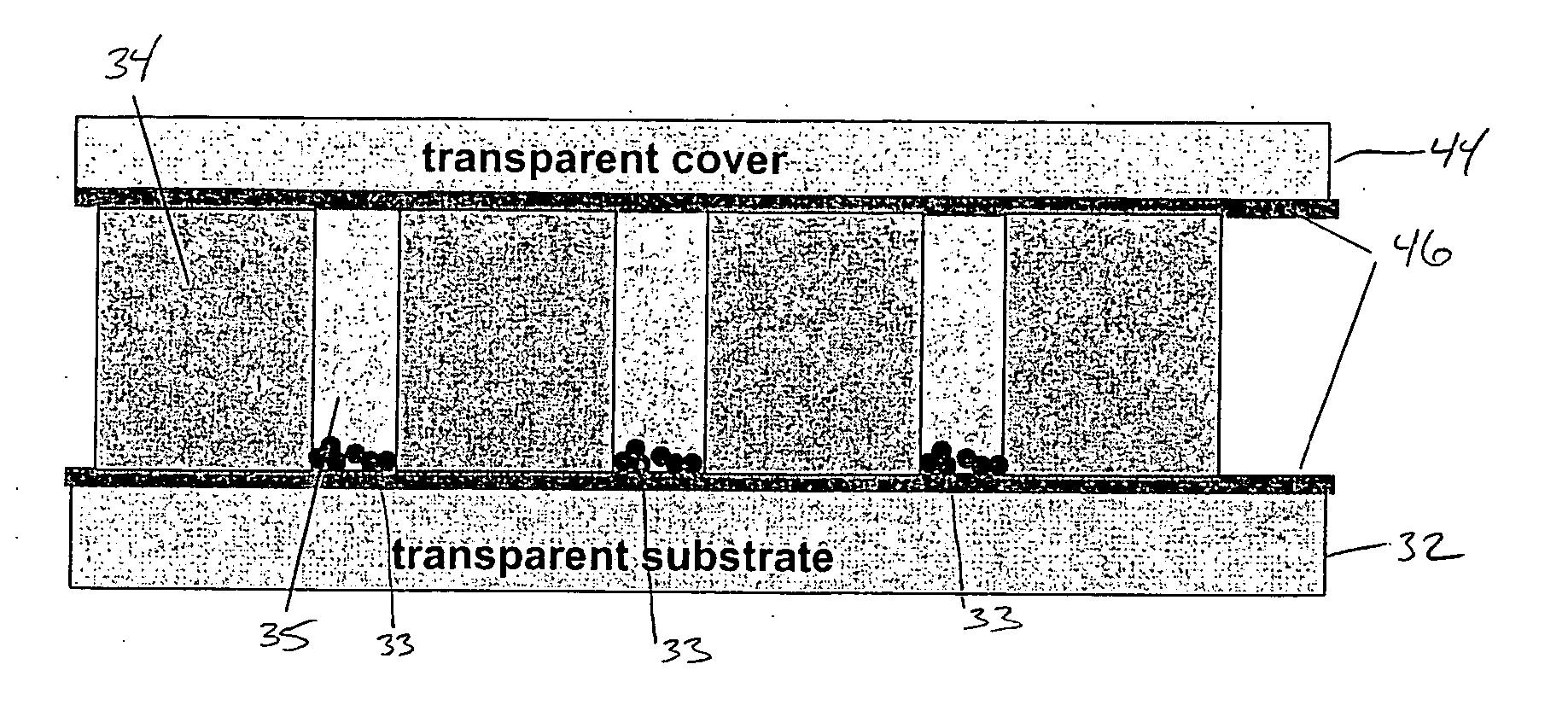
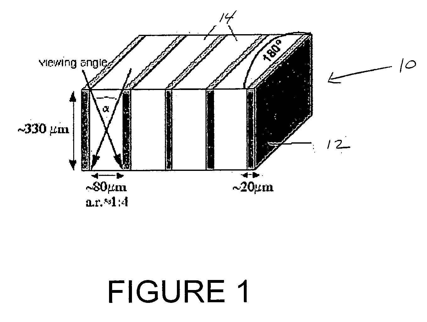
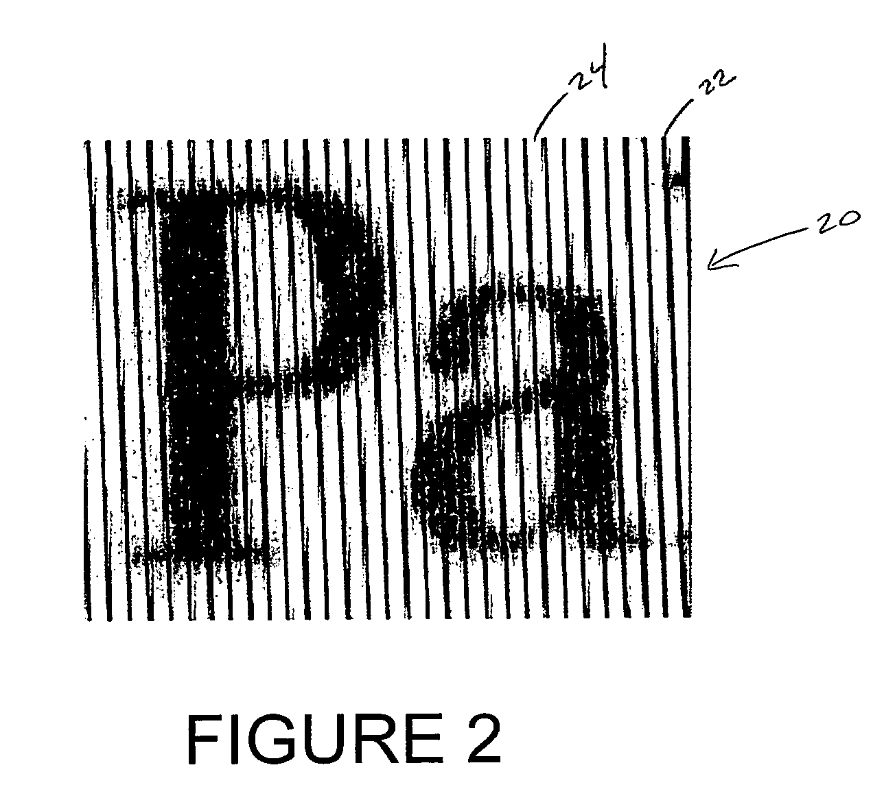
[0054] According to the presently described embodiments, a microfabricated light collimating screen is provided. The micro-fabricated screen, in one form, is made from a photo-imagable epoxy resin material, such as SU-8 (e.g., from Microchem Corp.) material. While SU-8 material is used in one form, any photopolymer or photo-polymerizable epoxy having a high aspect ratio will suffice, so long as it has a suitable cross-link density. The exemplary screen is operative to collimate light simultaneously in two dimensions. In many forms, improved degrees of collimation are also realized. The screen may be patterned on a substrate and fit to a particular application or it may be directly patterned onto image or light sensors or light sources in order to achieve direct collimation.

[0055] The contemplated configuration provides many other improvements over that which was heretofore known, including improved fabrication methods. These methods allow for large-area fabrication at relatively lo...


PUM

PropertyMeasurementUnit
Angleaaaaaaaaaa
Areaaaaaaaaaaa
Transparencyaaaaaaaaaa

Abstract

A microfabricated light collimating screen is provided. A microfabricated screen, in one form, is made from a photopolymer such as SU-8 material. It is able to collimate light in two dimensions and for improved degrees of collimation. It may also be directly patterned onto image sensors or light sources in order to achieve direct collimation. The fabrication method is large-area compatible and inexpensive. The proposed screens may be useful for position detection of objects, such as in the paper mover, in printers and copy machines.

Description

CROSS REFERENCE TO RELATED PATENTS AND APPLICATIONS [0001] This application is related to U.S. application Ser. No. 10 / 980,334, filed Nov. 4, 2004, entitled “Elastic Microchannel Collimating Arrays and Method of Fabrication,” naming David K. Biegelsen as an inventor.BACKGROUND [0002] By way of background, light collimating screens are used in many optical applications. These devices typically control the direction of light passing through the screen. [0003] Light control films, or light collimating screens, have various applications such as contrast enhancement and improved sunlight readability for displays. Light collimating screens are also useful for ensuring confidential viewing on computer monitors so that unauthorized observers will have the line of sight blocked. Such films are also used to direct light to where it is needed and away from where it is not, e.g., to hide the light source in incandescent lighting. [0004] Other industrial applications of light collimating screens...

Claims


Application Information

Patent Timeline
IPC IPC(8): G03B21/56G02B6/06
CPCG02B6/08Y10S385/901
Inventor DANIEL, JURGEN H.BIEGELSEN, DAVID K.
Owner E INK CORPORATION
Why Eureka
Try Eureka