Connector for two-way optical communications

a technology of optical communication and connector, which is applied in the direction of optical elements, semiconductor lasers, instruments, etc., can solve the problems of deteriorating the optical property of the connector, large loss of optical coupling, and deteriorating the optical property of the light guide, so as to achieve stable and excellent optical properties, low optical coupling loss, and the effect of low cos

Inactive Publication Date: 2007-06-21
HOSIDEN CORP
View PDF2 Cites 0 Cited by
  • Summary
  • Abstract
  • Description
  • Claims
  • Application Information

AI Technical Summary

Benefits of technology

[0023] In view of this problem, the present invention has as its object the provision of a connector for two-way optical communications, the connector enabling reliable alignment (optical axis alignment) between light guides and a light-emitting device and a light-receiving device and achieving a stable and excellent optical property.
[0029] It is therefore possible to obtain a connector for two-way optical communications with a low optical coupling loss and a stable and excellent optical property.

Problems solved by technology

However, in the fixation structure of such light guides, a stress caused by the press-fit may act on the light guides and the optical property (optical function) of the light guides may be deteriorated by the influence of the stress.
Such misalignment causes a large loss of optical coupling between the light guides 21 and 22 and the light-emitting device 30 and the light-receiving device 40 and seriously deteriorates the optical property of the connector.

Method used


Image

  • Connector for two-way optical communications
  • Connector for two-way optical communications
  • Connector for two-way optical communications

Examples


Embodiment Construction

[0057] A preferred embodiment of the present invention will now be described below.

[0058] The embodiment of the present invention will be described based on examples with reference to the accompanying drawings. Parts corresponding to those of FIGS. 1 to 5 are indicated by the same reference numerals and the detailed explanation thereof is omitted.

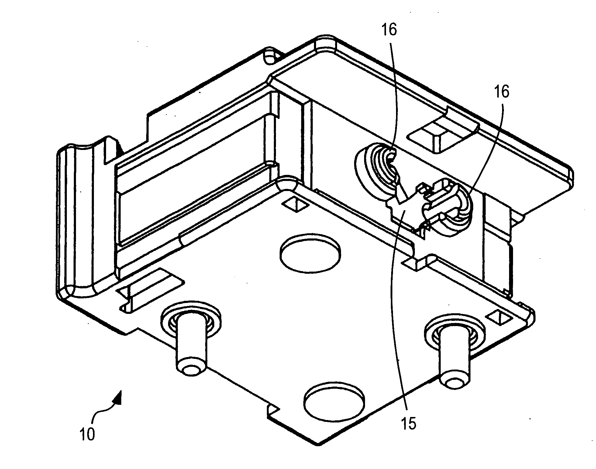
[0059]FIG. 6 shows the appearance of a connector for two-way optical communications of the present invention. FIG. 7 shows a state in which the connector is disassembled into parts. FIG. 8 shows the partially disassembled connector which is viewed from the front of the connector, that is, in the opposite direction from FIG. 7.

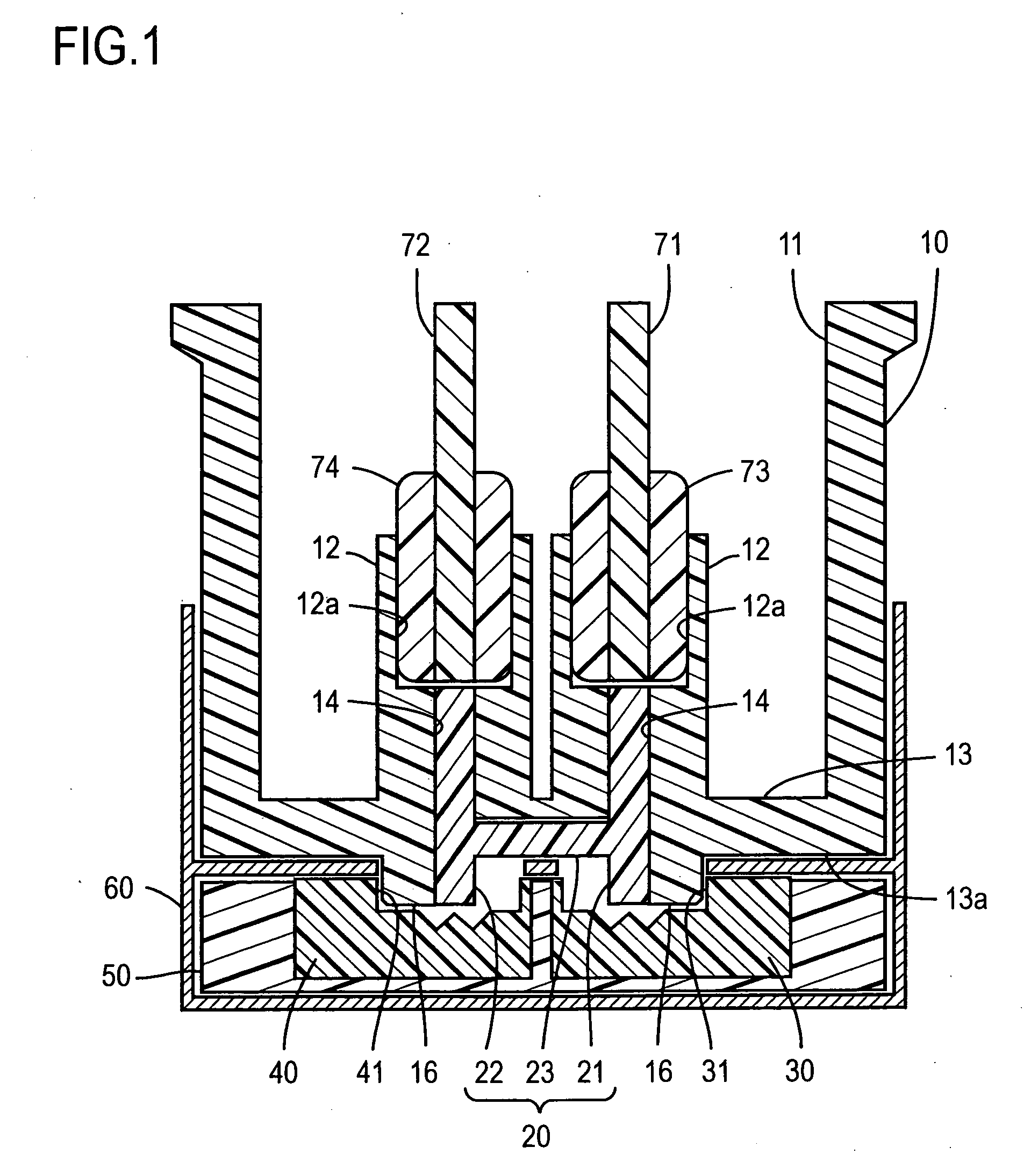
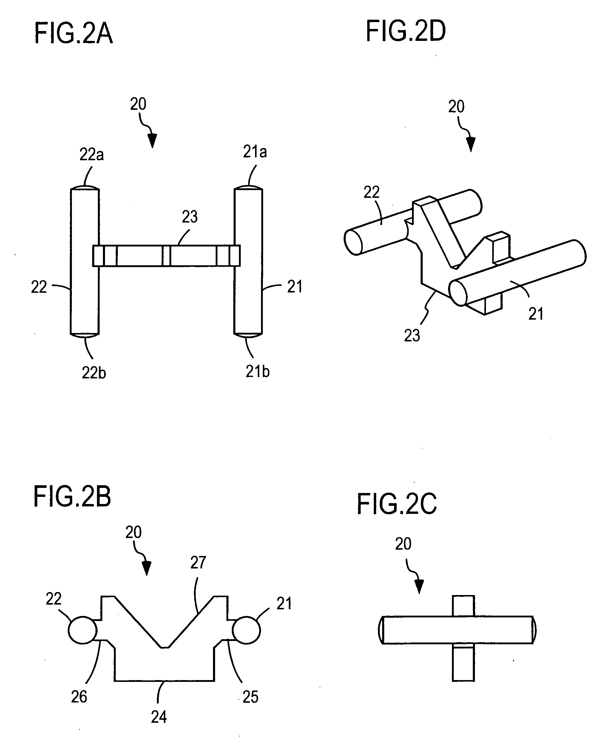
[0060] In this example, as shown in FIG. 7, the connector comprises a receptacle body 10, a light guide unit 20, a light-emitting device 30, a light-receiving device 40, a device holder 50, and a shield cover 60 as in the connector of FIGS. 1 to 5. Further, the connector comprises two attachments 81. The two attachm...


PUM


Abstract

Attachments are respectively attached to one ends of a pair of light guides, which are integrally formed via a connecting portion, such that the attachments surround the one ends of the light guides. The one ends protrude from a rear face of a receptacle body and are opposed to a light-emitting device and a light-receiving device, respectively. The attachments are inserted and positioned in guide holes formed respectively on the light-emitting device and the light-receiving device, and the optical axes of the pair of light guides and the optical axes of the light-emitting device and the light-receiving device are aligned with each other.

Description

BACKGROUND OF THE INVENTION [0001] 1. Field of the Invention [0002] The present invention relates to a connector for two-way optical communications, the connector being connected to an optical plug holding a transmitting optical fiber and a receiving optical fiber. [0003] 2. Description of the Related Art [0004] This kind of connector generally includes a light-emitting device, a light-receiving device, and light guides (light guiding members) for optically connecting the light-emitting device and the light-receiving device to the transmitting optical fiber and the receiving optical fiber of the opposite optical plug. For example, Patent document 1 (Japanese Patent Application Laid-Open No. 2001-133665) describes a connector configure thus. [0005] In the connector of Patent document 1, a pair of receiving tubes is formed in a connector housing. The optical fibers (ferrules are placed on the ends of the fibers) of an optical plug are inserted in the receiving tubes. Light guides (ref...

Claims


Application Information

Patent Timeline
Patent Type & Authority Applications(United States)
IPC IPC(8): G02B6/36G02B6/42H01L31/0232H01S5/022
CPCG02B6/421G02B6/4246G02B6/4292G02B6/36G02B6/38
Inventor TAKEHARA, NAOYANAKAGAWA, HIROSHIISODA, TAKESHI
Owner HOSIDEN CORP
Why Eureka
Try Eureka