Radio frequency identification (RFID) antenna integration techniques in mobile devices

a technology of radio frequency identification and mobile devices, applied in the direction of burglar alarm mechanical actuation, burglar alarm by hand-portable object removal, instruments, etc., can solve the problems of limited space available for antenna integration and fully integrated

Inactive Publication Date: 2007-06-21
SYMBOL TECH INC
View PDF11 Cites 137 Cited by
  • Summary
  • Abstract
  • Description
  • Claims
  • Application Information

AI Technical Summary

Benefits of technology

[0009] Methods, systems, and apparatuses for mobile devices and antennas thereof, are described herein. A mobile device includes functionality for communicating with one or more wireless networks, and includes RFID reader functionality. A single antenna of the mobile device accommodates wireless network communication functionality and RFID reader functionality.

Problems solved by technology

As the mobile devices get smaller, the available space to integrate the antennas becomes more limited.
Currently, RFID systems are deployed primarily as accessories to mobile devices, and are not fully integrated therein.

Method used


Image

  • Radio frequency identification (RFID) antenna integration techniques in mobile devices
  • Radio frequency identification (RFID) antenna integration techniques in mobile devices
  • Radio frequency identification (RFID) antenna integration techniques in mobile devices

Examples


example rfid system embodiment

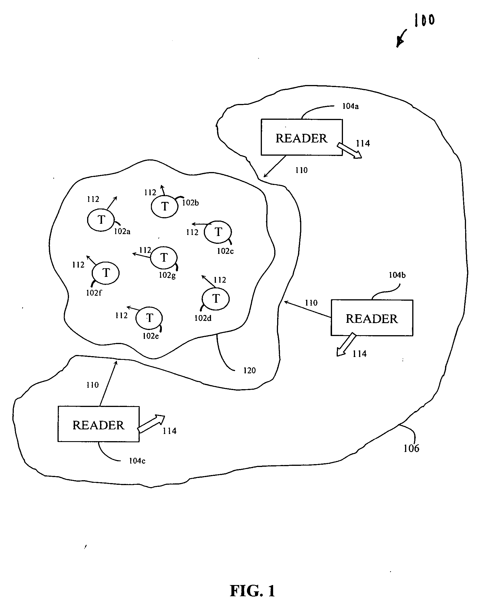
[0030] Before describing embodiments of the present invention in detail, it is helpful to describe an example RFID communications environment in which the invention may be implemented. FIG. 1 illustrates an environment 100 where RFID tag readers 104 communicate with an exemplary population 120 of RFID tags 102. As shown in FIG. 1, the population 120 of tags includes seven tags 102a-102g. It will be apparent to those skilled in the relevant art(s) that population 120 may include any number of tags 102.

[0031] Environment 100 includes either a single reader 104 or a plurality of readers 104, such as readers 104a-104c. A reader 104 may be requested by an external application to address the population of tags 120. Alternatively, reader 104 may have internal logic that initiates communication, or may have a trigger mechanism that an operator of reader 104a uses to initiate communication.

[0032] As shown in FIG. 1, readers 104 transmit an interrogation signal 110 having a carrier frequenc...


PUM


Abstract

Methods, systems, and apparatuses for mobile devices and antenna thereof, are described herein. A mobile device include RFID reader functionality, and functionality for communicating with one or more wireless networks. A single antenna of the mobile device accommodates the network communication functionality and the RFID reader functionality. The communications network is any type of communications network, including a personal area network (PAN), a local area network (LAN), a wide area network (WAN), or a cell phone network. An antenna pattern of the antenna may be configurable. For example, a gain of the antenna may be varied, the antenna pattern may be shaped, directed, and/or polarized, the antenna pattern may be steered, and/or the antenna pattern may be ranged.

Description

BACKGROUND OF THE INVENTION [0001] 1. Field of the Invention [0002] The present invention relates to radio frequency identification (RFID) systems, and in particular to mobile devices having RFID functionality. [0003] 2. Background Art [0004] As the applications and capabilities of mobile devices continue to expand, the amount of electronics required to support these applications and capabilities also increases. With the advent of wireless communications systems, mobile devices can be required to support multiple radio solutions. Example such radio solutions include Personal Area Networks (PAN), Local Area Networks (LAN), and Wide Area Networks (WAN). [0005] The antennas required to support each of these different radios in the mobile device are designed to specific requirements in terms of power, frequency, bandwidth, gain, directionality, etc. The location of the antennas within the mobile device is also crucial to obtain proper antenna performance. As the mobile devices get small...

Claims


Application Information

Patent Timeline
Patent Type & Authority Applications(United States)
IPC IPC(8): H04B1/44
CPCG06K19/0723
Inventor WULFF, THOMASKNADLE, RICHARD T. JR.
Owner SYMBOL TECH INC
Why Eureka
Try Eureka