
Tile cutter

a tile cutter and cutting board technology, applied in the field of tile cutters, can solve the problems of deteriorating limited general limitation of the maximum cutting range of the tile cutter, so as to facilitate the transportation of the tile cutter and fix the relative position. the effect of destroying the portability of the tile cutter

Inactive Publication Date: 2007-06-28
LI JIANGNAN
View PDF0 Cites 14 Cited by
  • Summary
  • Abstract
  • Description
  • Claims
  • Application Information

AI Technical Summary

Benefits of technology

[0006] The object of the present invention is to provide a tile cutter with simple configuration and a locking device having dual locking functions.
[0012] The operator can easily fix the first worktable and the second worktable of the worktable assembly together and conveniently fix the relative position between the worktable assembly and the support frame while fixing the relative position between the first worktable and the second worktable, so that it is convenient to transport of the tile cutter without destroying the portability of the tile cutter.

Problems solved by technology

However, the maximum cutting range of the tile cutter is generally limited by the dimension of the worktable of the cutter.
But the maximum cutting range of the tile cutter is still limited by the length of the rail.
The common method for increasing the cutting range is to increase the length of the rail, which results in deteriorating the portability of the tile cutter.

Method used


Image

  • Tile cutter
  • Tile cutter
  • Tile cutter

Examples


Embodiment Construction

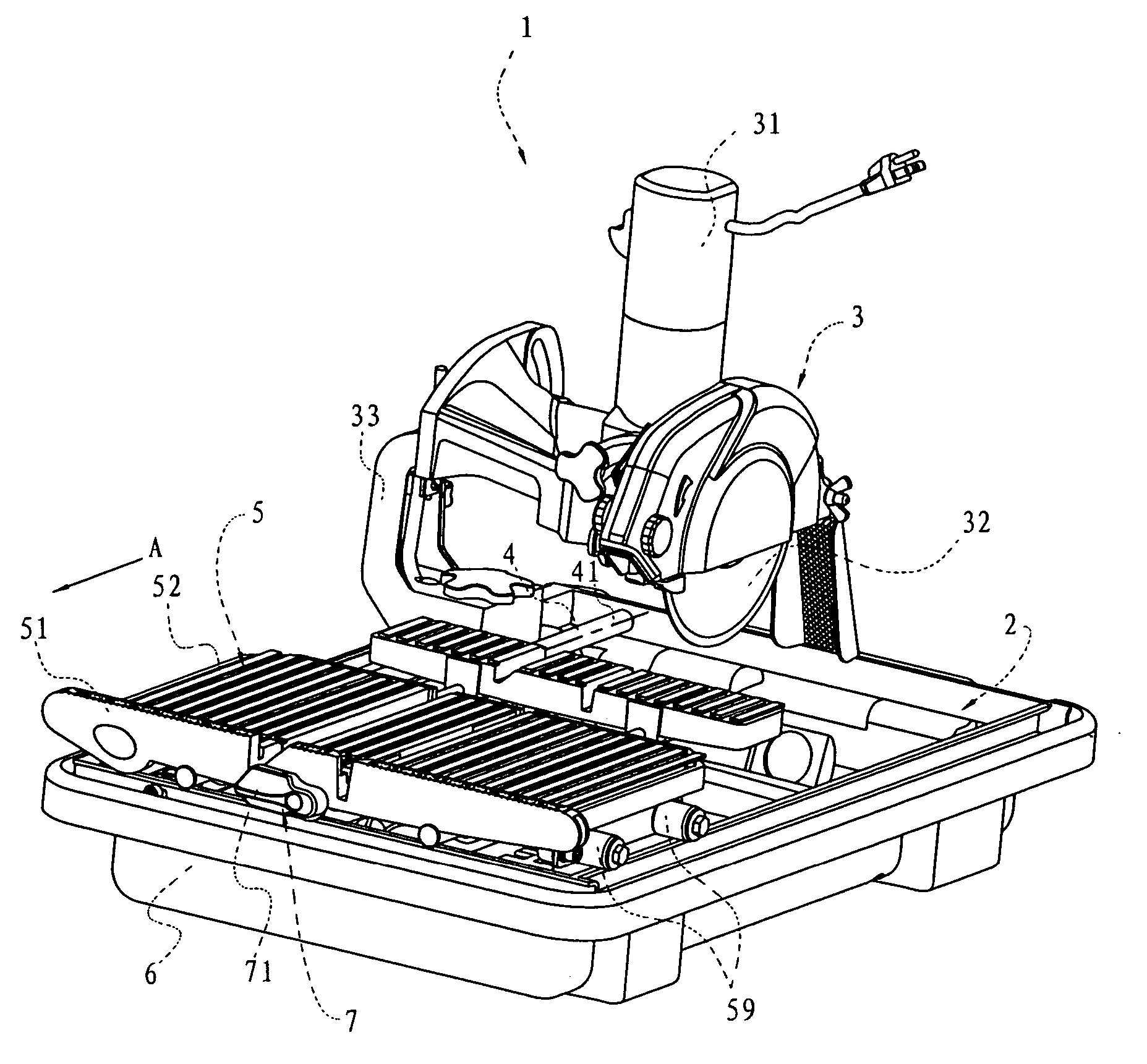
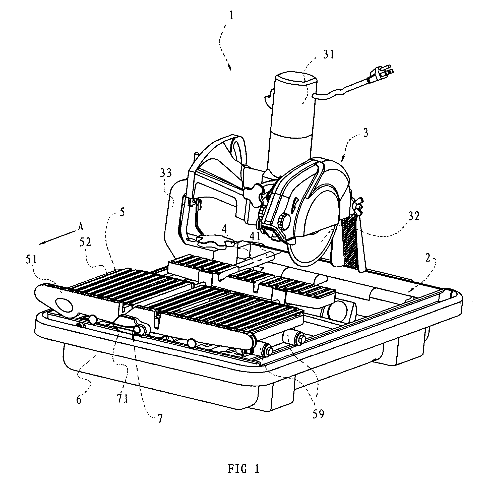
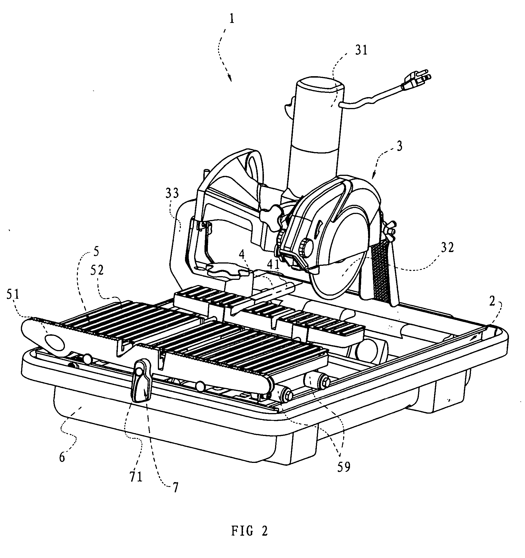
[0021]FIGS. 1-8 show a tile cutter of a preferred embodiment according to the present invention. The tile cutter 1 comprises a support frame 2, a cutting device 3, a rail 4, a worktable assembly 5 and a water tray 6.

[0022] The stabilizing device 100 further comprises an adjusting device 128 acting between the base plate 102 and the second supporting wall 106, for adjusting the position of the second supporting wall 106 on the base plane 108 so that the second supporting wall 106 is movable and can be fixed on a position between the first supporting wall 104 and the second side edge 112 of the base plate 102, for stabilizing crown moldings with different width. In the preferred embodiment, the support frame 2 is substantially rectangular. The rail 4 has a cylindrical outer surface and two ends of it are disposed on the support frame 2 (as shown in FIGS. 1-3). The rail 4 has a longitudinal axis 41. One ordinary skilled in the art will easily recognize that the support frame and the r...


PUM

PropertyMeasurementUnit
lengthaaaaaaaaaa
sizeaaaaaaaaaa
widthaaaaaaaaaa

Abstract

The present invention is to provide a tile cutter in simple configuration having a locking device of dual locking functions. The tile cutter comprises a support frame, a cutting device mounted on the support frame, at least one rail disposed on the support frame, a worktable assembly slidably installed in or on a first rail of the at least one rail and a water tray. The first rail has a longitudinal axis. The worktable assembly comprises a first worktable and a second worktable. One of the support frame and the water tray is mounted or placed on the other one of the support frame and the water tray. A locking device is mounted between the first worktable and the second worktable. The locking device comprises a first locking portion and a second locking portion.

Description

CROSS-REFERENCE TO RELATED APPLICATIONS [0001] This application claims priority to Chinese Application No. 200520140151.3 filed Dec. 22, 2005, the entire disclosure of which is incorporated herein by reference. Priority to this application is claimed under 35 U.S.C. §§ 119, 120 and / or 365. FEDERALLY SPONSORED RESEARCH OR DEVELOPMENT [0002] Not Applicable. TECHNICAL FIELD [0003] The present invention relates to a tile cutter, in particular to a tile cutter the cutting range of which is increased. BACKGROUND OF THE INVENTION [0004] In a conventional tile cutter, usually, a tile is directly put on a worktable fixed relative to the cutter to be cut. However, the maximum cutting range of the tile cutter is generally limited by the dimension of the worktable of the cutter. [0005] To overcome the disadvantage of the conventional tile cutter, in market, a tile cutter which comprises a rail or rails arranged on the base of the tile cutter and a worktable slidably connected to the rail or rai...

Claims


Application Information

Patent Timeline
Patent Type & Authority Applications(United States)
IPC IPC(8): B28D1/04
CPCB23D47/025B28D1/047B28D7/04E04F21/0076B23D45/02
Inventor LI, JIANGNAN
Owner LI JIANGNAN
Learn More