Method and apparatus for encoding and decoding picture signal, and related computer programs

Inactive Publication Date: 2007-06-28
VICTOR CO OF JAPAN LTD
View PDF1 Cites 74 Cited by
  • Summary
  • Abstract
  • Description
  • Claims
  • Application Information

AI Technical Summary

Benefits of technology

[0069] This invention has an advantage mentioned below. In this invention, multi-view video is encoded through signal processing which includes view interpolation. The view interpolation generates a prediction signal (a view-interpolated signal) for a picture of interest which relates to one viewpoint on the basis of reference pictures relating to other viewpoints. The reference pictures are those resulting from encoding and decoding original pictures relating to t

Problems solved by technology

The sending side obtains a relative parallax between the two selected images, and also a prediction error therebetween.
The transmission of the information representing the position change quantities would cause a reduction in system transm

Method used


Image

  • Method and apparatus for encoding and decoding picture signal, and related computer programs
  • Method and apparatus for encoding and decoding picture signal, and related computer programs
  • Method and apparatus for encoding and decoding picture signal, and related computer programs

Examples


first embodiment

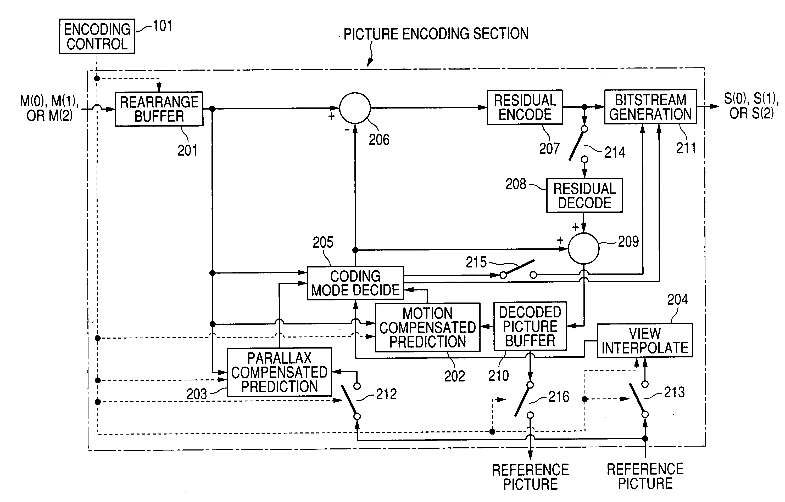
[0094]FIG. 4 shows a multi-view video encoding apparatus in a system according to a first embodiment of this invention. The encoding apparatus of FIG. 4 includes an encoding control section 101, picture encoding sections 102, 103, and 104, and a multiplexing section 105.

[0095] With reference to FIG. 4, there are data or a signal M(0) representing a sequence of pictures taken from a first viewpoint, data or a signal M(1) representing a sequence of pictures taken from a second viewpoint, and data or a signal M(2) representing a sequence of pictures taken from a third viewpoint. For an easier understanding, the data or signal M(0) is also referred to as the video sequence M(0) or the first-viewpoint video sequence M(0). The data or signal M(1) is also referred to as the video sequence M(1) or the second-viewpoint video sequence M(1). The data or signal M(2) is also referred to as the video sequence M(2) or the third-viewpoint video sequence M(2). The first, second, and third viewpoint...

second embodiment

[0172]FIG. 10 shows a multi-view video encoding apparatus in a system according to a second embodiment of this invention. The encoding apparatus of FIG. 10 is similar to that of FIG. 4 except for design changes mentioned hereafter.

[0173] The encoding apparatus of FIG. 10 includes a computer system 10 having a combination of an input / output port 10A, a CPU 10B, a ROM 10C, and a RAM 10D. The encoding apparatus further includes the multiplexing section 105. The input / output port 10A in the computer system 10 receives the video sequences M(0), M(1), and M(2). The computer system 10 processes the video sequences M(0), M(1), and M(2) into the bitstreams S(0), S(1), and S(2) respectively. The input / output port 10A outputs the bitstreams S(0), S(1), and S(2) to the multiplexing section 105.

[0174] The multiplexing section 105 multiplexes the bitstreams S(0), S(1), and S(2), the decoding time information (the decoding timing information), and the display time information (the display timing...

third embodiment

[0209]FIG. 14 shows a multi-view video encoding apparatus in a system according to a third embodiment of this invention. The encoding apparatus of FIG. 14 is similar to that of FIG. 4 except for design changes mentioned hereafter.

[0210] The encoding apparatus of FIG. 14 includes an encoding control section 701, picture encoding sections 702, 703, and 704, and a multiplexing section 705 which are basically similar to the encoding control section 101, the picture encoding sections 102, 103, and 104, and the multiplexing section 105 in FIG. 4. The encoding apparatus further includes a decoded-picture buffer (a decoded-picture buffer memory) 706 located outside the picture encoding sections 702, 703, and 704. The decoded-picture buffer 706 is used as a decoded-picture buffer 210 (see FIG. 6) in each of the picture encoding sections 102, 103, and 104. Accordingly, each of the picture encoding sections 702, 703, and 704 does not contain a decoded-picture buffer.

[0211] Decoded pictures g...


PUM


Abstract

A first-viewpoint picture is encoded. A first decoded picture is generated in the encoding of the first-viewpoint picture. A second-viewpoint picture is encoded. A second decoded picture is generated in the encoding of the second-viewpoint picture. View interpolation responsive to the first decoded picture and the second decoded picture is performed to generate a view-interpolated signal for every multi-pixel block. One is decided from different coding modes including coding modes relating to the view interpolation for every multi-pixel block. A prediction signal is generated in accordance with the decided coding mode. The prediction signal is subtracted from a third-viewpoint picture to generate a residual signal for every multi-pixel block. A signal representative of the decided coding mode and the residual signal are encoded to generate encoded data representing the third-viewpoint picture and containing the signal representative of the decided coding mode.

Description

BACKGROUND OF THE INVENTION [0001] 1. Field of the Invention [0002] This invention relates to a method, an apparatus, and a computer program for encoding signals representative of multi-view video taken from multiple viewpoints. In addition, this invention relates to a method, an apparatus, and a computer program for decoding encoded data representative of multi-view video taken from multiple viewpoints. [0003] 2. Description of the Related Art [0004] An MPEG (Moving Picture Experts Group) encoder compressively encodes a digital signal (data) representing a video sequence. The MPEG encoder performs motion-compensated prediction and orthogonal transform with respect to the video signal to implement highly efficient encoding and data compression. The motion-compensated prediction utilizes a temporal redundancy in the video signal for the data compression. The orthogonal transform utilizes a spatial redundancy in the video signal for the data compression. Specifically, the orthogonal t...

Claims


Application Information

Patent Timeline
IPC IPC(8): H04N7/12H03M7/36H04N19/50H04N13/00H04N19/51H04N19/513H04N19/59H04N19/597H04N19/60H04N19/61
CPCH04N13/0011H04N19/61H04N19/597H04N13/111
Inventor NAKAMURA, HIROYA
Owner VICTOR CO OF JAPAN LTD
Why Eureka
Try Eureka