
Apparatus, system, method, and program for visible light communication

a technology of visible light and apparatus, applied in the field of apparatus, system, method, program for visible light communication, can solve the problems of efficient utilization, discomfort and/or visual trouble for human beings, and achieve the effects of improving communication quality, convenient identification of apparatus beings, and satisfying usability

Inactive Publication Date: 2007-06-28
NEC CORP
View PDF16 Cites 173 Cited by
  • Summary
  • Abstract
  • Description
  • Claims
  • Application Information

AI Technical Summary

Benefits of technology

[0012] It is therefore an object of the present invention, which has been devised to remove the problems, to provide an apparatus, a system, a method, and a program for visible light communications in which the visible light having the feature of “visibility” is efficiently used in a communication process so that the communication state during the visible light communication is visually recognized.
[0042] In accordance with the present embodiments, by controlling the light emission state of the visible light radiated from the light emitting module, the communication state can be visually recognized. Thanks to the configuration in which the state of communication is recognizable during the visible light communication according to the light emission state of the visible light, the user can confirm the position of the communication apparatus existing in a ubiquitous fashion. It is also possible for the user to directly recognize the procedure of the communication process. This consequently provides the user with the feeling of security as well as satisfactory usability. Also, through intervention of the user having recognized the emission state of the visible light, it is possible to easily identify the apparatus being a partner of the visible light communication, and hence the communication quality is improved.

Problems solved by technology

For example, there does not exist a light emitting device that radiates light with high efficiency, and the visible light is visually uncomfortable and / or visually troublesome for the human beings.
That is, according to the technique described in these articles, it is not considered that one of the features of the visible light, namely, “visibility, is efficiently utilized.

Method used


Image

  • Apparatus, system, method, and program for visible light communication
  • Apparatus, system, method, and program for visible light communication
  • Apparatus, system, method, and program for visible light communication

Examples


first embodiment

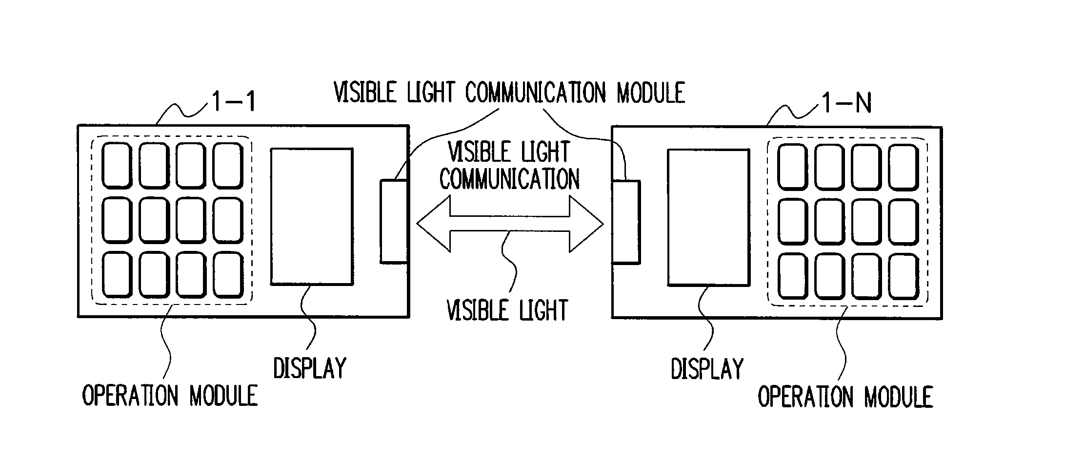
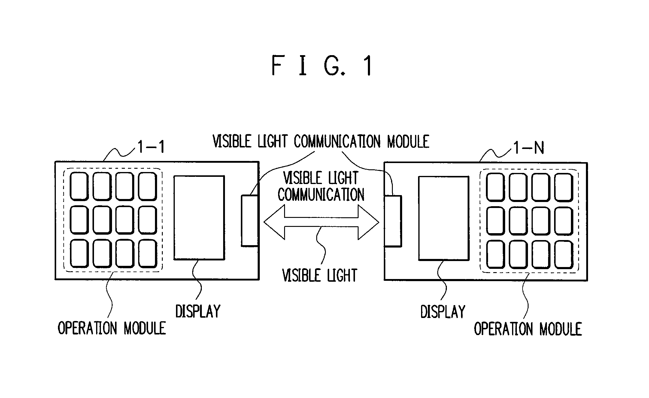
[0058] First, referring to FIG. 1, description will be given of the visible light communication system according to the first embodiment.

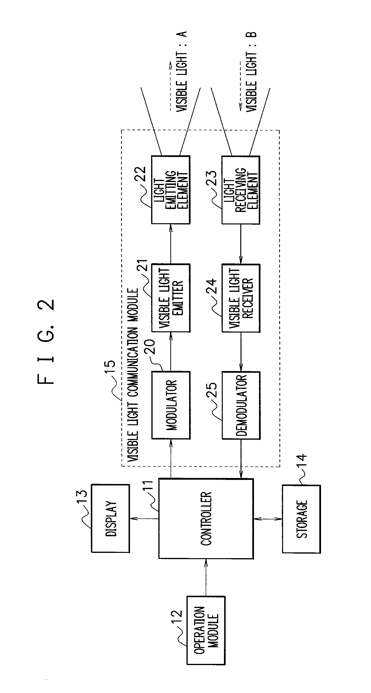
[0059] The communication system of the first embodiment includes a plurality of visual light communication apparatuses 1-1 to 1-N (N is a natural number) capable of conducting information communication using visible light. As the communication apparatus of the communication system, any unit capable of visible light communication is available. The available devices include, for example, a cellular phone, a Personal Digital Assistance (PDA), a Personal Computer (PC), a printer, imaging apparatuses such as a facsimile device, and family-use electric appliances such as a television set, an air conditioner, and an illumination device. Referring next to FIG. 2, description will be given of the visible light communication units 1-1 to 1-N employed in the first embodiment of the visible light communication system.

[0060] The visible light communication un...

second embodiment

[0099] Next, description will be given of a second embodiment of the visible light communication system As above, in the first embodiment of the visible light communication system, the visible light communication apparatus 1-1 on the transmission side changes during the visible light communication the emission state (the color) of the visible light from the light emitting element 22 according to the change in the communication state (the communication process). In the second embodiment, the visible light communication apparatus (1-1 to 1-N) on the reception side alters the emission state or the color of the visible light emitted from the light emitting element 22 according to the change in the communication state or the communication process. It is therefore possible for an operator of the transmitter-side communication unit 1-1 to visually recognize which one of the receiver-side communication units 1-2 to 1-N is conducting communication with the communication unit 1-1. Referring n...

third embodiment

[0121] Next, description will be given of a third embodiment of the visible light communication system.

[0122] The third embodiment has an aspect that during the visible light communication between the transmitter-side visible light communication unit 1-1 and the receiver-side visible light communication units 1-2 to 1-N, the communication unit 1-1 changes the emission zone of the visible light according to a change in the communication state. For example, as can be seen from FIG. 7A, when a plurality of communication units 1-2 to 1-N exist in the emission zone of the communication unit 1-1, the unit 1-1 receives visible light from the plural communication units 1-2 to 1-N. This may cause interference between the lights. To cope with this difficulty, during the visible light communication, the communication unit 1-1 varies the emission zone of the communicating module 15 to thereby receive the visible light from one of the communication units 1-2 to 1-N. This prevents the interferen...


PUM


Abstract

A visible light communication apparatus enables an operator to visually recognize a communication state during visual light communication. The apparatus includes a light emitting section which emits visible light and which includes a modulator, a visible light emitter, a light emitting element and an emission control section which includes a controller and which controls an emission state of the visible light from the light emitting section. The apparatus controls the emission state according to the communication state. It is hence possible for the operator to visually perceive the communication state during the visible light communication.

Description

BACKGROUND OF THE INVENTION [0001] 1. Field of the Invention [0002] The present invention relates to an apparatus, a system, a method, and a program for conducting communication of information by using visible light visible for human beings. [0003] 2. Description of the Related Art [0004] In the conventional information communication, there have been employed infrared rays and radio waves invisible for the human beings for the following reasons. For example, there does not exist a light emitting device that radiates light with high efficiency, and the visible light is visually uncomfortable and / or visually troublesome for the human beings. [0005] However, with visible light, the human can visually recognize an area or a zone in which the visible light can be received. Therefore, when compared with the infrared rays and the radio waves, the visible light is superior in usability and is more suitable for entertainment depending on purposes of the use thereof. The visible light is the ...

Claims


Application Information

Patent Timeline
IPC IPC(8): H04B10/00H04B10/112H04B10/11
CPCH04B10/1143H04B10/116
Inventor FUJIWARA, RYUHEI
Owner NEC CORP
Learn More