Developing unit and image forming device

a technology of image forming device and developing unit, which is applied in the direction of instruments, electrographic process equipment, optics, etc., can solve the problems of damage to the protruding portion, and achieve the effect of preventing damage to the movement member

Active Publication Date: 2007-06-28
BROTHER KOGYO KK
View PDF6 Cites 40 Cited by
  • Summary
  • Abstract
  • Description
  • Claims
  • Application Information

AI Technical Summary

Benefits of technology

[0015] This developing unit can be moved between a movement member housing position and a movement member protruding position. When the developing unit is in an attached state with respect to the image forming device main body, the movement member protrudes from the developer case. As a result, the movement member (i.e. the developing unit) can be pushed in the predetermined direction. When the developing unit is not in an attached state with respect to the image forming device main body, the movement member can be maintained in the housing position. As a result, the phenomenon can be prevented wherein strong force is applied unexpectedly to the movement member. With this developing unit, damage to the movement member can be prevented.

Problems solved by technology

The protruding portion could be damaged if strong force is applied unexpectedly to the protruding portion of the developing unit while this developing unit is not attached to the image forming device main body (the laser printer main body in the above example).

Method used


Image

  • Developing unit and image forming device
  • Developing unit and image forming device
  • Developing unit and image forming device

Examples


first embodiment

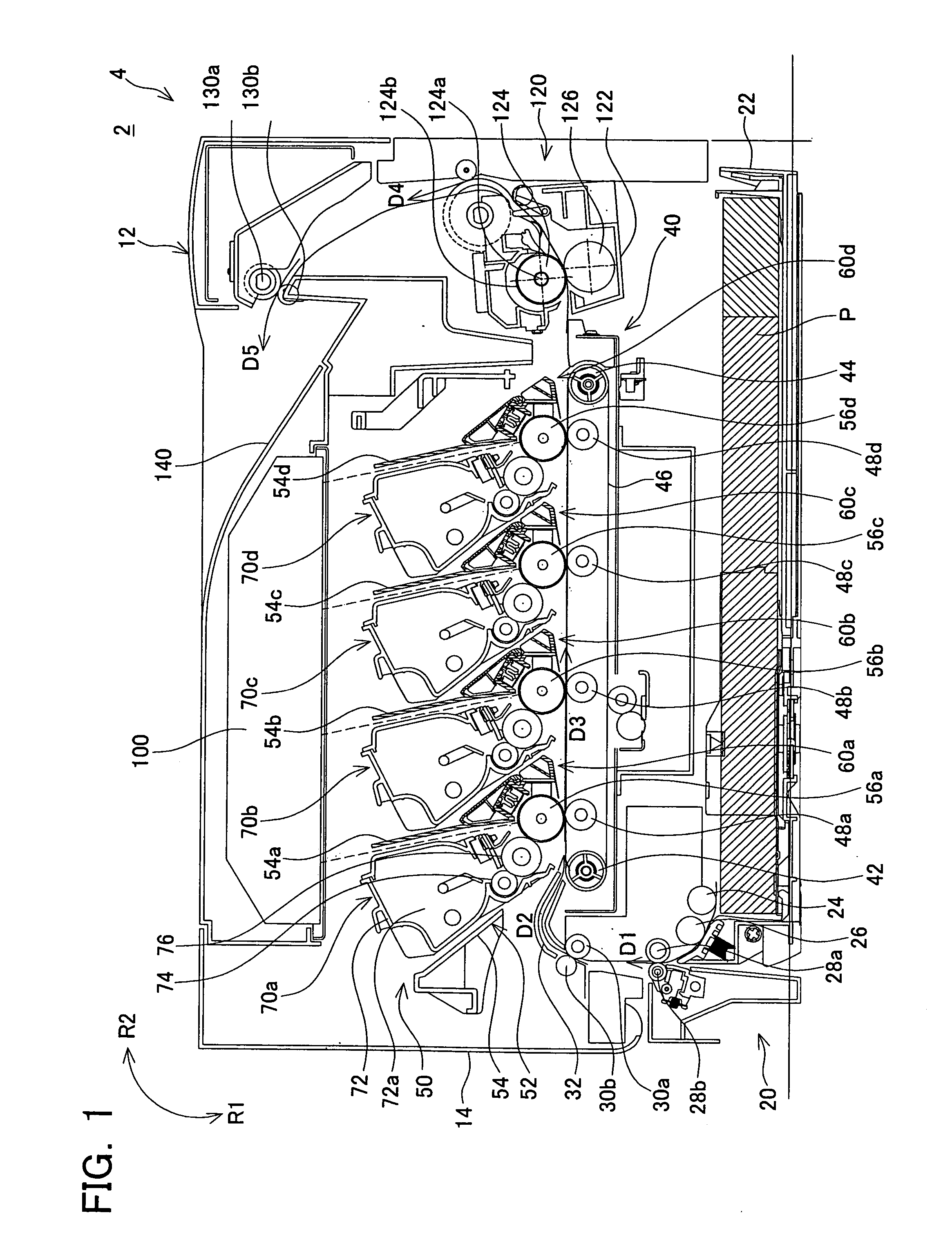
[0046] A laser printer 2 of the present embodiment will be described with reference to the figures. FIG. 1 shows a cross-sectional view of the laser printer 2. Below, the laser printer 2 may be referred to simply as the printer 2. In the present embodiment, the left direction of FIG. 1 is the front side of the printer 2.

[0047] The printer 2 has a printer main body 4, and developing units 70a, 70b, 70c, and 70d attached detachably to the printer main body 4. The printer main body 4 has a main case 12. The main case 12 includes a plurality of plate-shaped members. In FIG. 1, a front side cover member 14 is shown that constitutes a part of the main case 12. The front side cover member 14 can swing in the directions shown by the arrows R1 and R2. Swinging the front side cover member 14 in the direction of the arrow R1 opens the main case 12. In this state, a drum unit 50 (to be described) can be removed from the main case 12. Swinging the front side cover member 14 in the direction of ...

second embodiment

[0117] Only parts differing from the first embodiment will be described. In the present embodiment, the configuration of the developing units differs from that of the first embodiment. FIG. 16 is a perspective view of a developing unit 270 of the present embodiment.

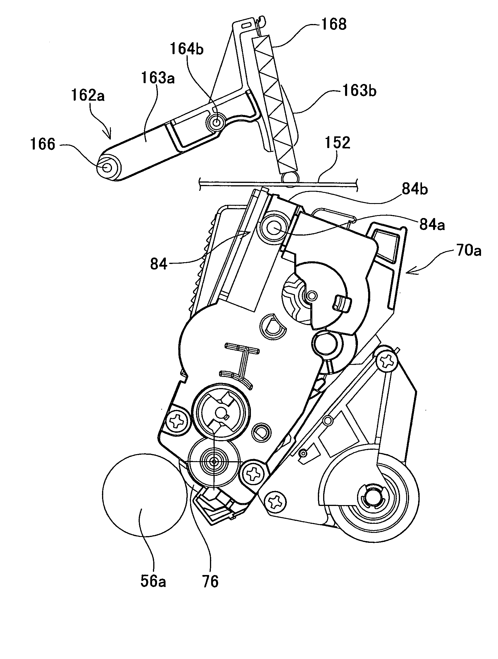
[0118] A pair of long holes 280a and 280b is formed in a front surface 280 of a toner case 272. The long holes 280a and 280b extend in a rotation axis direction of the developing roller 76. In the state shown in FIG. 16, a pair of movement members 284 is housed within a toner case 272. FIG. 17 shows the developing unit 270 in a state where the movement members 284 are protruding.

[0119] As shown in FIG. 17, the pair of movement members 284 each has a tubular portion 284a, a body 284b, a protruding part 284c, and a regulating part 284d. The tubular portion 284a is fixed to the body 284b. The protruding part 284c extends from the body 284b. The protruding part 284c of the right side movement member 284 protrudes to the ext...


PUM


Abstract

A developing unit is to be attachable to and detachable from an image forming device main body. The developing unit is provided with a developer case, a developing roller coupled with the developer case, and a movement member coupled with the developer case. The movement member is capable of moving between a housing position where the movement member is substantially housed inside the developer case and a protruding position where the movement member protrudes beyond the developer case. The movement member is positioned at the protruding position and pushed by the image forming device main body in a predetermined direction while the developing unit is being attached to the image forming device main body.

Description

CROSS-REFERENCE TO RELATED APPLICATION [0001] This application claims priority to Japanese Patent Application No. 2005-373792, filed on Dec. 27, 2005, the contents of which are hereby incorporated by reference into the present application. BACKGROUND OF THE INVENTION [0002] 1. Field of the Invention [0003] The present invention relates to an image forming device for forming images using developer. Further, the present invention relates to a developing unit of the image forming device. Moreover, the present invention also relates to an image forming device main body attached to the developing unit. [0004] 2. Description of the Related Art [0005] Image forming devices that utilize developer to print onto a recording medium (printing paper, for example) are well known. For example, a laser printer comprises a laser printer main body, and a developing unit attached detachably thereto. [0006] The laser printer main body has a main case including a space for housing the developing unit, a...

Claims


Application Information

Patent Timeline
Patent Type & Authority Applications(United States)
IPC IPC(8): G03G15/08
CPCG03G2221/163G03G2221/1654G03G2221/1815G03G15/0868G03G21/1676G03G15/0875G03G21/1623
Inventor HAYAKAWA, ATSUSHI
Owner BROTHER KOGYO KK
Why Eureka
Try Eureka