Compact suture punch with malleable needle

Inactive Publication Date: 2007-06-28
ARTHREX
View PDF91 Cites 45 Cited by
  • Summary
  • Abstract
  • Description
  • Claims
  • Application Information

AI Technical Summary

Benefits of technology

[0016] The needle differs from standard needles in terms of size, shape and material properties. In beneficial embodiments, the needle is shorter than standard needles, generally 10 to 13 mm in length, and has a cross-section which may be circular or non-circular, including rectangular with at least two parallel sides. The rectangular needles may have varying thicknesses and have a cross-section that ranges from substantially square to substantially flat. Additionally, the needle is made of a malleable material permitting it to be shaped within the handheld instrument and to retain its form while passing through tissue. The needle may also return to its form after passing through the tissue or once any bending force has been removed. Similarly, the distal portion of the trocar may be malleable, thereby permitting shaping within the handheld instrument.
[0017] In contrast to existing suture punches in which the needle or shuttle undergoes only an elastic deformation during use and the functional un-constrained shape of the needle or shuttle is produced during manufacture, the needle of the disclosed device may be inelastically formed to its functional shape during use, allowing the needle to traverse a nonlinear path. More particularly, when passing through the distal tip of the hand instrument, the needle may be inelastically formed by a radial path within the instrument, the plane of the radius being substantially unparallel to the tissue through which the suture is being passed. The formation of this radius is facilitated by the aforementioned parallel sides of the needle cross-section which are constrained by the instrument in such a manner as to place them essentially in the plane of the tissue.
[0020] After the proximal end of the needle exits the instrument, the needle may be propelled further along its radial path by the force-supplying mechanism, such as a trocar. Additionally, the distal portion of the mechanism may be formed to a radial shape by the instrument in the same manner as the needle. Additionally, the radial shapes of the needle and mechanism may also be coplanar. Engagement of the mechanism with the needle after the needle passes from the instrument may be facilitated by mating surfaces of the mechanism and needle, shaped, for example, to prevent radial or lateral displacement of the needle proximal and mechanism distal surfaces. The mechanism may also be engaged with the needle in a manner that connects the mechanism and needle together such that the connection is capable of being broken after the needle has exited the instrument.
[0024] Accordingly, in one embodiment, the present invention provides suturing instrumentation for suturing tissue having a malleable needle portion having a sharpened distal tip and constructed and arranged to deliver a length of suture material to the tissue; a handheld instrument having a passageway and having a distal end terminating in a nonlinear portion having a first radius; and a force-supplying structure for applying a force to the needle portion, wherein the force-supplying structure includes a distal end capable of pushing the malleable needle portion through the nonlinear portion, such that when the distal end of the handheld instrument is positioned proximate to the tissue to be sutured and the malleable needle portion is pushed by the distal end of the force-supplying structure through the nonlinear portion, the needle portion is deformed, thereby causing the needle portion to deliver the suture material to the tissue.

Problems solved by technology

More particularly, when passing through the distal tip of the hand instrument, the needle may be inelastically formed by a radial path within the instrument, the plane of the radius being substantially unparallel to the tissue through which the suture is being passed.

Method used


Image

  • Compact suture punch with malleable needle
  • Compact suture punch with malleable needle
  • Compact suture punch with malleable needle

Examples


Embodiment Construction

[0146] The present invention is more particularly described in the following examples that are intended to be illustrative only since numerous modifications and variations therein will be apparent to those skilled in the art. As used in the specification and in the claims, the singular form “a,”“an,” and “the” may include plural referents unless the context clearly dictates otherwise. Also, as used in the specification and in the claims, the term “comprising” may include the embodiments “consisting of and ” consisting essentially of.”

[0147] The present invention will now be further described through the following drawings. It is to be understood that these drawings are non-limiting and are presented to provide a better understanding of various embodiments of the present invention and are not intended to represent every possible embodiment of the present invention.

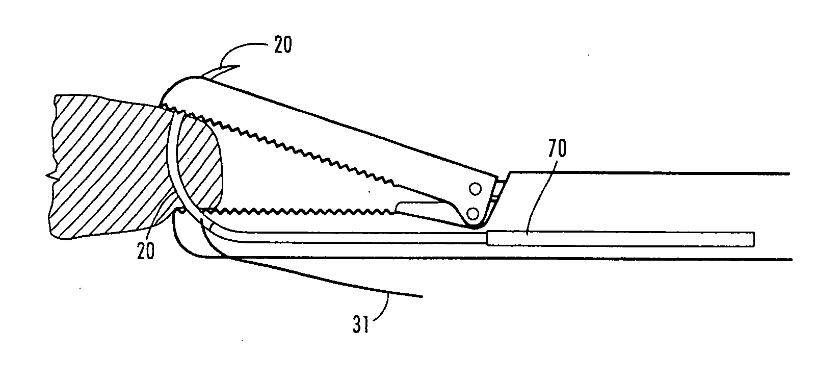
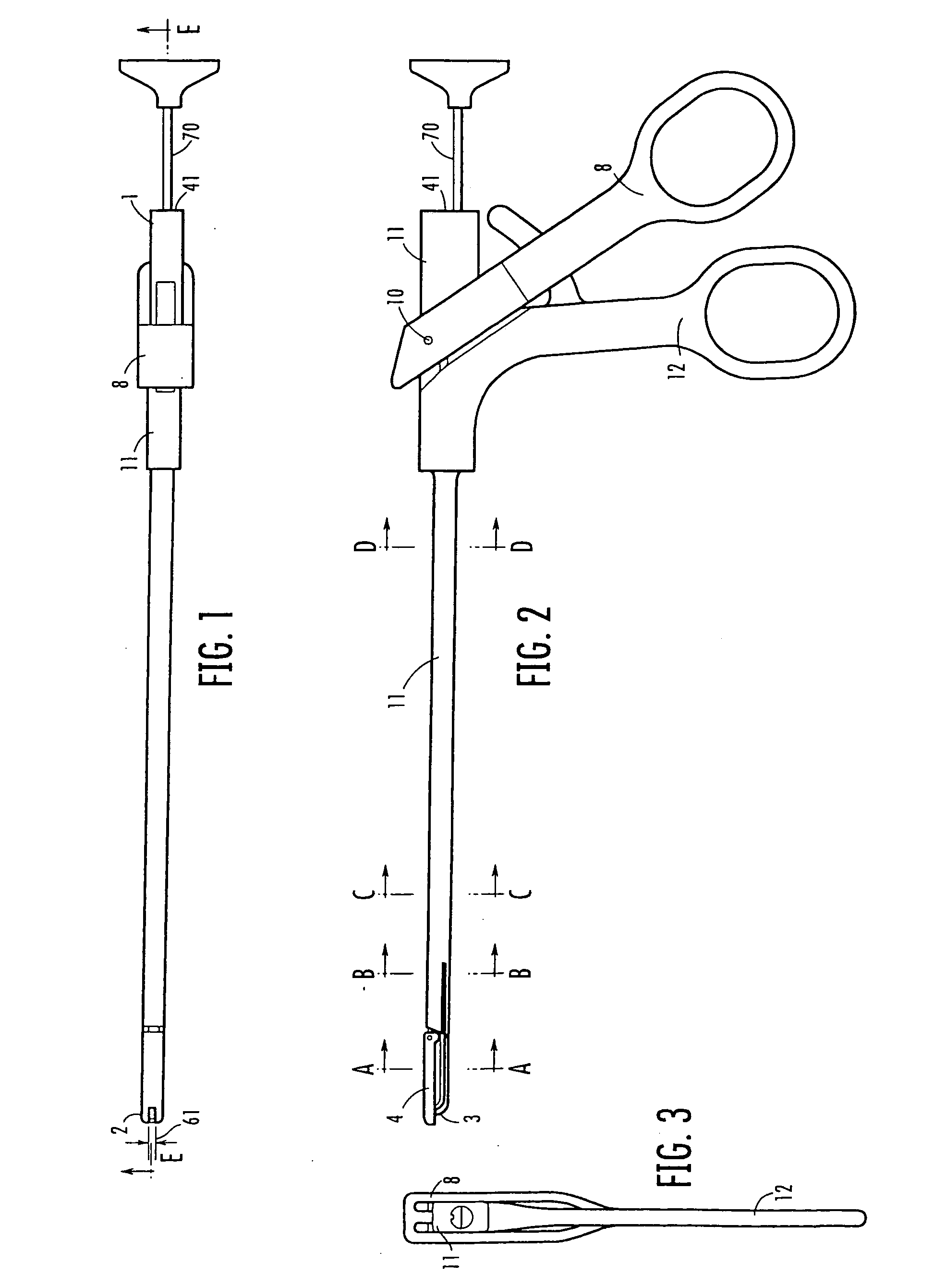
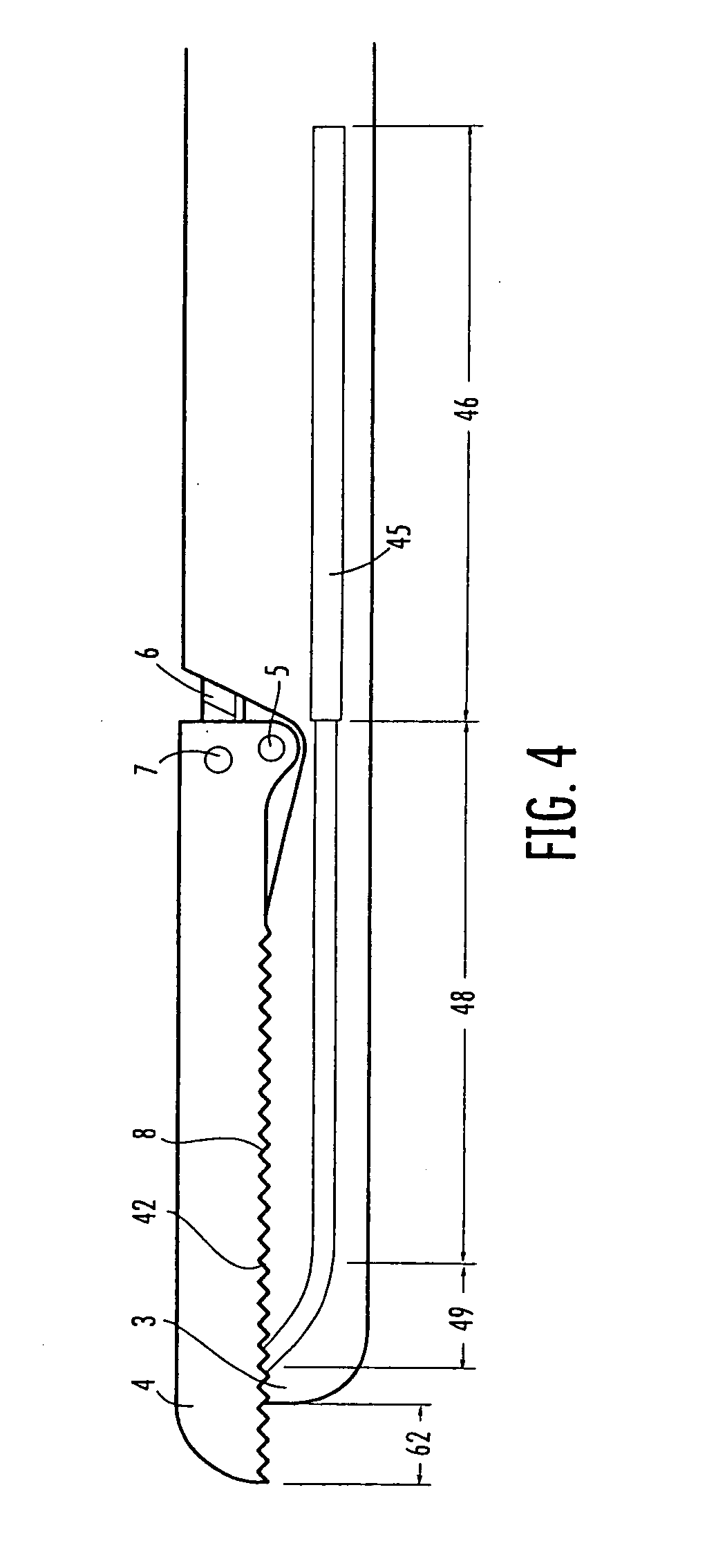
[0148] Referring to the drawings, as best seen in FIGS. 1 through 9, the instrument body 11 has a proximal end 1 and a d...


PUM


Abstract

A suture punch system that is capable of directly passing braided suture through tissue in a simple, one-step process. The system includes three principle components: a malleable needle capable of delivering the suture to the tissue, a handheld instrument for grasping tissue and controlling needle placement, and a force-supplying mechanism to supply the force required for needle placement. Needle deformation begins at the tip of the instrument, which beneficially includes a curved segment. As the distal tip of the needle pierces the tissue, it continues its radial path through the tissue. When the proximal end of the needle exits from the instrument, the needle may be radial in shape and traverses an essentially radial path through the tissue. Once the needle has passed entirely through the tissue, it may be retrieved using the jaws of the punch or another instrument.

Description

REFERENCE TO RELATED APPLICATION [0001] This application is a continuation application of U.S. patent application Ser. No. 10 / 815,338, filed Apr. 1, 2004, which a continuation-in-part application of U.S. patent application Ser. No. 10 / 165,468, filed Jun. 7, 2002, which claims priority to U.S. Provisional Patent Application Ser. No. 60 / 310,220, filed Aug. 6, 2001.FIELD OF THE INVENTION [0002] This invention relates generally to surgical suturing and, in particular, to improved articles, instrumentation, and methods therefore. BACKGROUND OF THE INVENTION [0003] Suture passing is problematic for the arthroscopic surgeon because the braided suture preferred by most arthroscopists cannot be pushed through a cannulated instrument. Braided suture must be pulled into location because applying a push force causes the braid to expand in diameter, thereby wedging in the instrument. [0004] Various solutions have been devised for passing braided suture. The Caspari Suture Punch (Linvatec Corpora...

Claims


Application Information

Patent Timeline
Patent Type & Authority Applications(United States)
IPC IPC(8): A61B17/04A61B17/00A61B17/06A61B17/062A61B17/28
CPCA61B17/0469A61B17/0482A61B17/06061A61B17/06066A61B17/062A61B17/0625A61B17/29A61B2017/00946A61B2017/0496A61B2017/06028A61B2017/2926
Inventor MORRIS, JOHN K.VAN WYK, ROBERT A.
Owner ARTHREX
Why Eureka
Try Eureka