Knee prostheses

Inactive Publication Date: 2007-06-28
MCMINN DEREK JAMES WALLACE
View PDF23 Cites 53 Cited by
  • Summary
  • Abstract
  • Description
  • Claims
  • Application Information

AI Technical Summary

Benefits of technology

[0016] As, in one embodiment, the metallic base plate part of the device, the second part, makes low friction sliding contact with the patellar component of the device, then the patella with its attached soft tissues is free medio-l

Problems solved by technology

The patellofemoral joint is a troublesome area in conventional total knee replacement design.
A significant number of patients are left with discomfort from the patellofemoral region following total knee replacement and others have failure such as lateral patellar mal-tracking, wear through of polyethylene patellar components, fracture of patellar components, loosening of components and fracture of the patella bone itself, requiring revision surgery.
However because this type of articular surface is highly conforming to the femoral component design that it is matched to, a fixed bearing of this design would not all

Method used


Image

  • Knee prostheses
  • Knee prostheses
  • Knee prostheses

Examples


Embodiment Construction

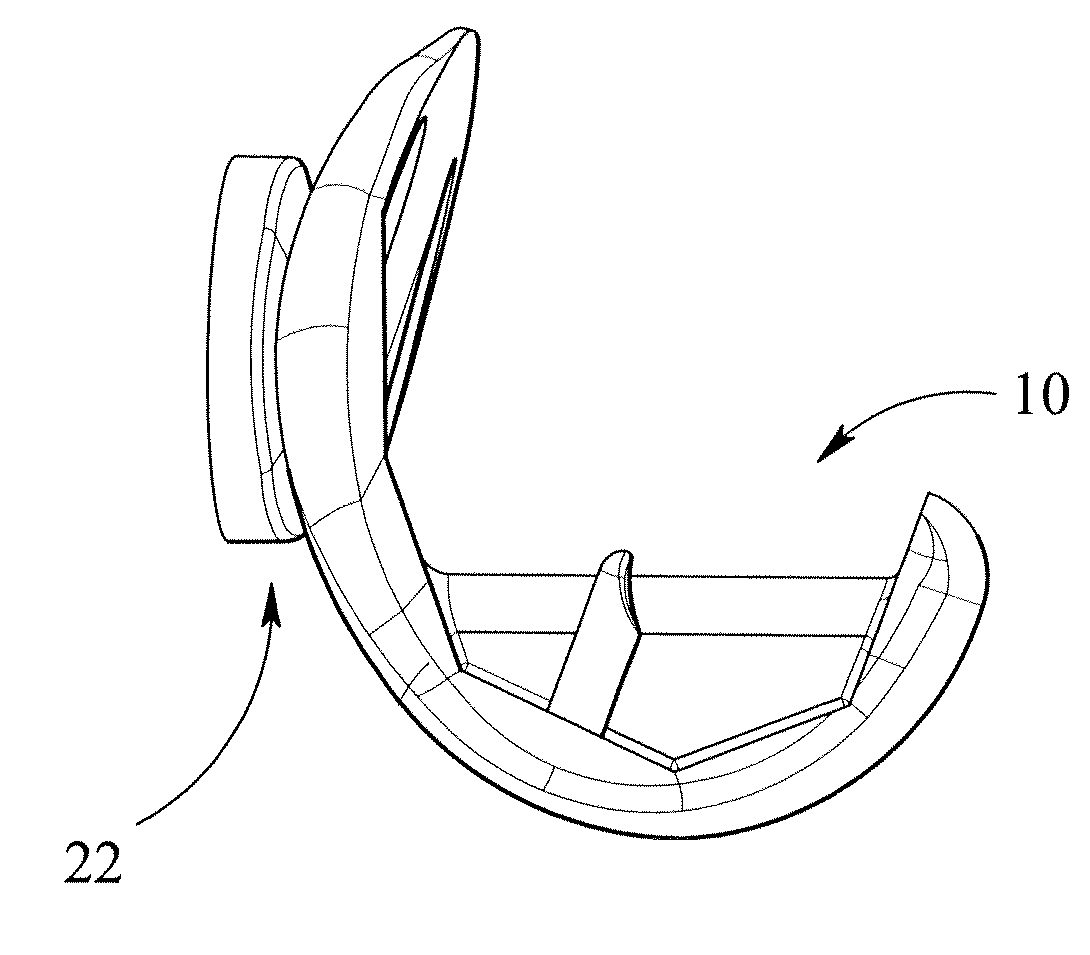
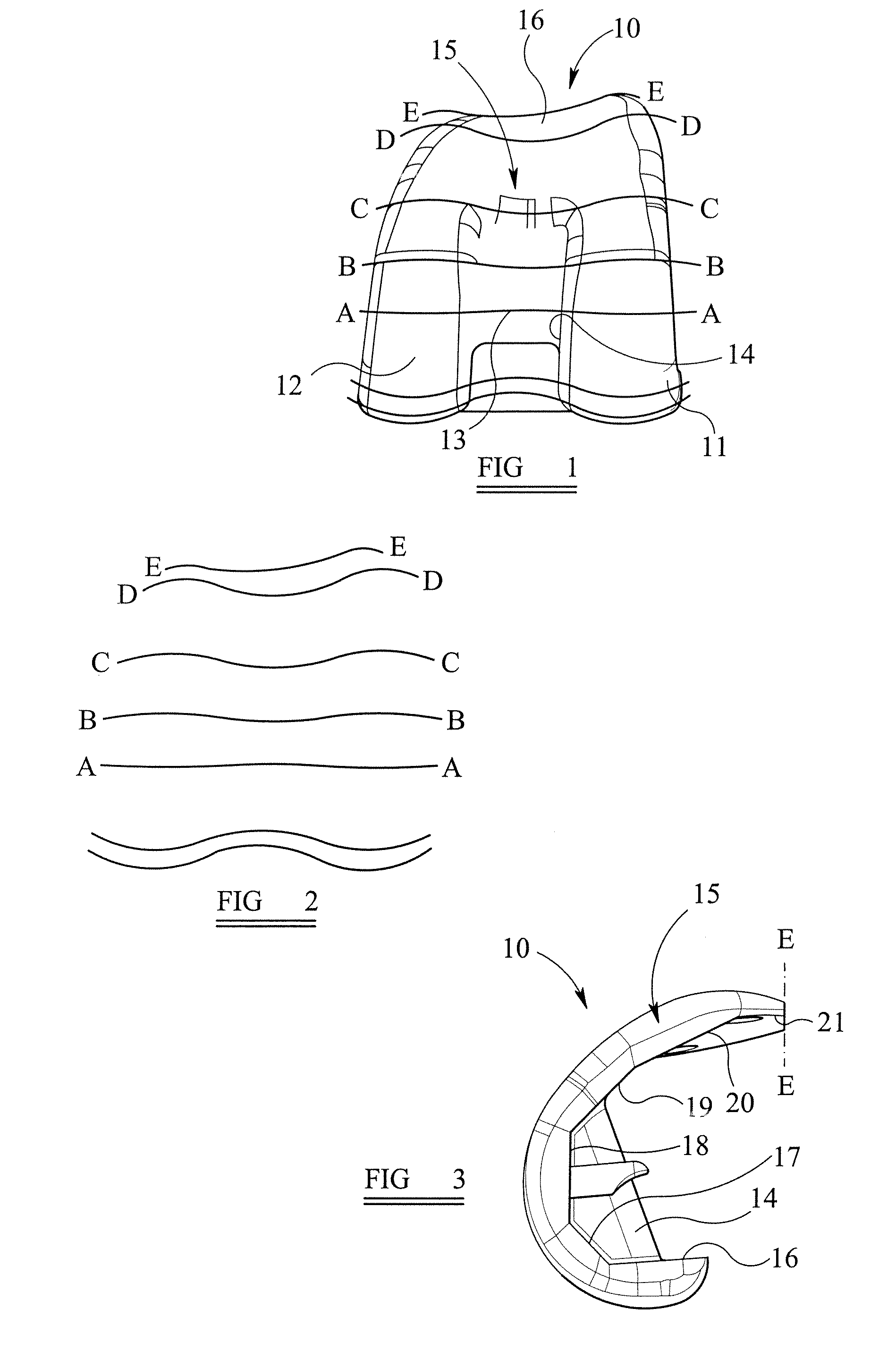
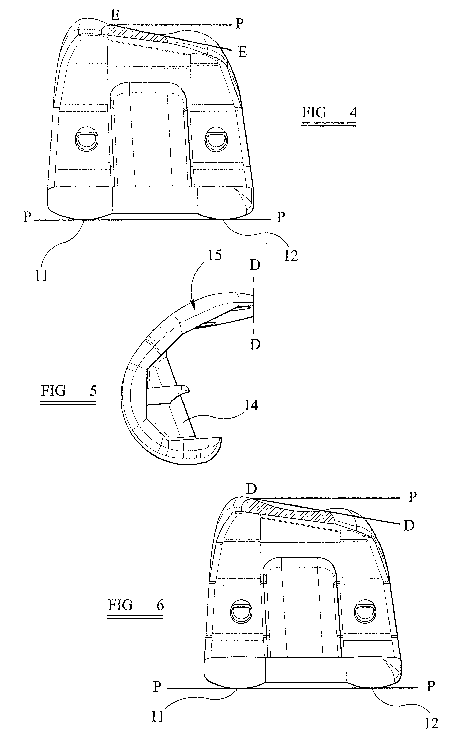
[0064]FIG. 1 shows a femoral component 10 of a knee prosthesis, the femoral component 10 comprising lateral and medial condyles 11, 12 respectively, between which is an open area 13 which, in this embodiment, is enclosed laterally and longitudinally by an intercondylar box 14. However this box could be omitted in an alternative embodiment. Extending away from the condyles 11, 12 and box 14 is a patellar flange 15, having a central patellar groove 16 extending from the box 14 to the free end of the flange 15. As shown, for example, in FIG. 3, the overall internal surface of the femoral component 10 is formed by six discrete flat surfaces 16 to 21 respectively, these, in use, matching six corresponding flat cut surfaces of the patient's femur. This particular arrangement of six flat surfaces may be formed as defined in the Applicant's co-pending UK Published Patent Application No: 2426200.

[0065] According to a first aspect of the invention, as shown best in FIGS. 1 and 2, a twist is ...


PUM


Abstract

A total knee prosthesis comprises a femoral component and a patellar component. The femoral component has a patellar flange into which is built a twist or roller coaster configuration. The patellar component has an off-set dome with respective lateral and medial facets. The configuration of the patellar flange resists forces from a medial to a lateral direction, whilst the lateral and medial facets of the patellar component are respectively shaped to allow area contact and line contact respectively with the femoral component. Also disclosed is a device for intra-operative checking of patellar tracking to allow correct insertion of the femoral and patellar components.

Description

FIELD OF THE INVENTION [0001] This invention relates to improvements in or relating to knee prostheses, and is particularly concerned with the patellofemoral interface. BACKGROUND OF THE INVENTION [0002] The patellofemoral joint is a troublesome area in conventional total knee replacement design. A significant number of patients are left with discomfort from the patellofemoral region following total knee replacement and others have failure such as lateral patellar mal-tracking, wear through of polyethylene patellar components, fracture of patellar components, loosening of components and fracture of the patella bone itself, requiring revision surgery. [0003] In order to obviate the point loading and high wear using a conventional domed polyethylene patellar button, U.S. Pat. No. 4,309,778 discloses a highly conforming patellar button giving area contact. However because this type of articular surface is highly conforming to the femoral component design that it is matched to, a fixed ...

Claims


Application Information

Patent Timeline
IPC IPC(8): A61F2/38
CPCA61F2/3859A61F2/3877A61F2/4657A61F2/4684A61F2002/4658A61F2/461
Inventor MCMINN, DEREK JAMES WALLACE
Owner MCMINN DEREK JAMES WALLACE
Why Eureka
Try Eureka