
Method and apparatus for investigating a borehole with a caliper

a technology of calipers and boreholes, applied in the field of methods and apparatus for investigating boreholes with calipers, can solve the problems of difficult accurate interpretation of data from regions of formations with dirty fluids, limited information can miss important irregularities on the sides of formations, etc., and achieve accurate projection of the interaction of the sides and accurate determination of the volume of concrete

Active Publication Date: 2007-07-05
LOADTEST
View PDF11 Cites 15 Cited by
  • Summary
  • Abstract
  • Description
  • Claims
  • Application Information

AI Technical Summary

Benefits of technology

[0005] Embodiments of the present invention relate to a caliper and method for mapping the dimensions and topography of a formation such as the sidewall of a borehole. Examples of formations in which embodiments of the invention can be used include, but are not limited to, an oil, gas, pile borehole or barrette that has been drilled or excavated into the earth. Such dimensional and topographic information can allow more accurate interpretation of test devices positioned in the pile created within the borehole and can allow an accurate determination of the volume of concrete needed to fill the pile. Such information can also allow more accurate projections of the interaction of the side of the pile with the side of the borehole, especially when the formation is filled with opaque stabilizing fluids whose density often varies with depth.

Problems solved by technology

However, such limited information can miss important irregularities in the sides of the formation.
In addition, data from regions of the formation having dirty fluids can be difficult to accurately interpret.

Method used


Image

  • Method and apparatus for investigating a borehole with a caliper
  • Method and apparatus for investigating a borehole with a caliper

Examples


Embodiment Construction

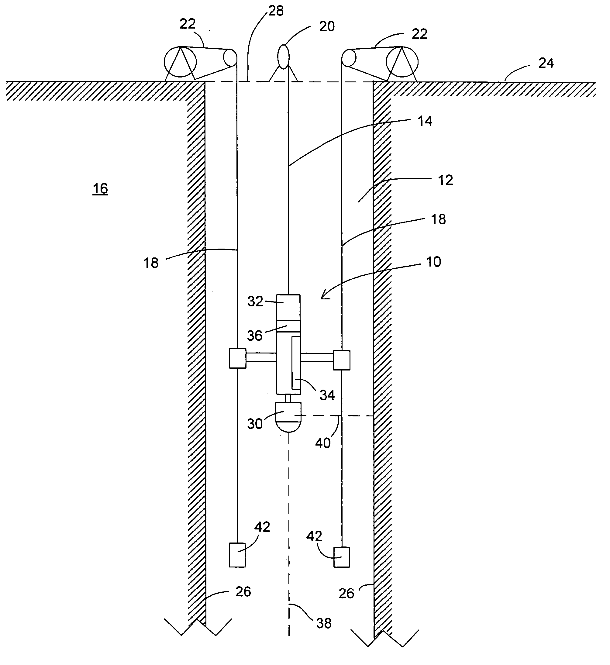
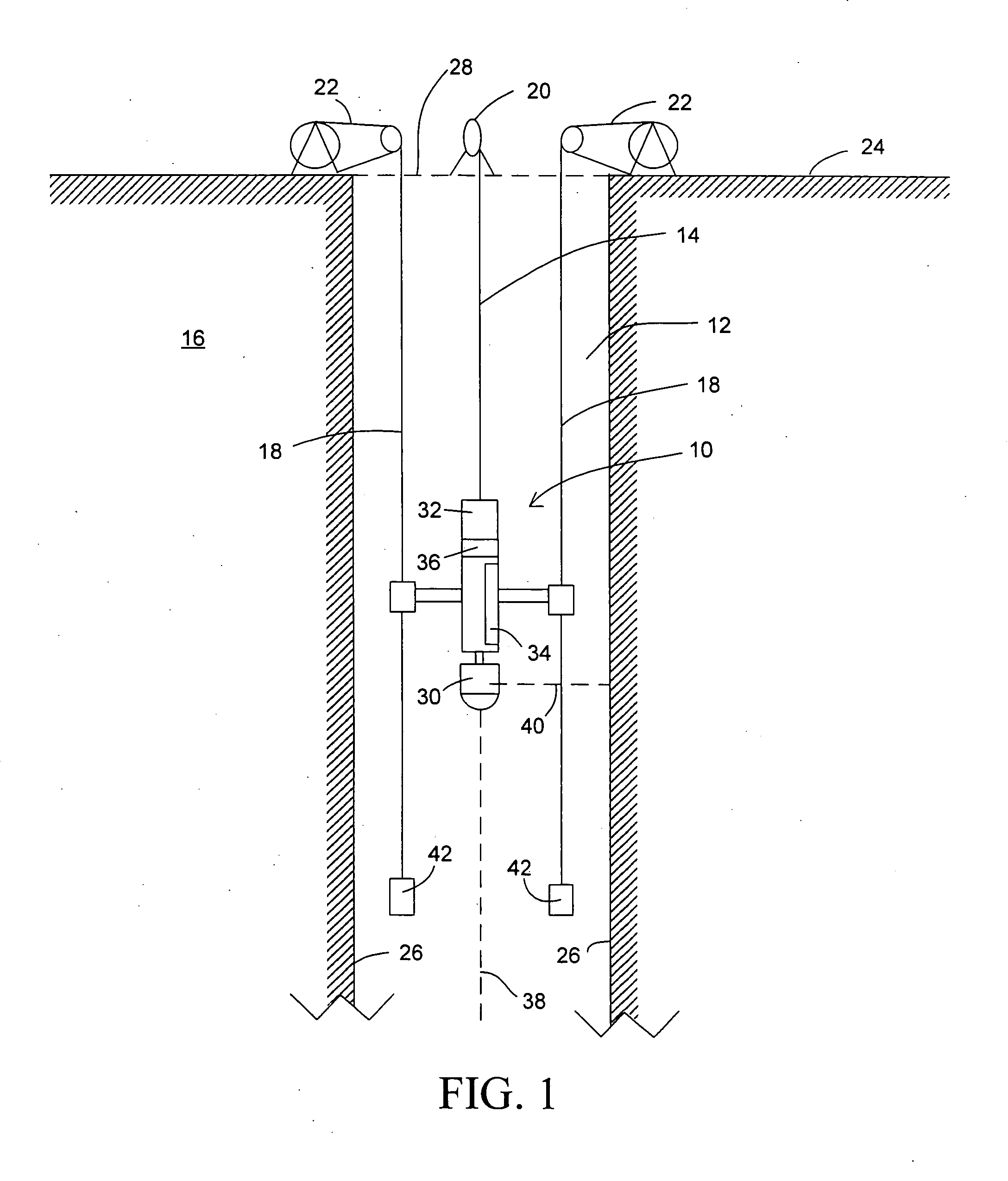
[0007] Embodiments of the present invention relate to a caliper and method for mapping the dimensions and topography of a formation such as the sidewall of a borehole. Examples of formations in which embodiments of the invention can be used include, but are not limited to, an oil, gas, pile borehole or barrette that has been drilled or excavated into the earth. Such dimensional and topographic information can allow more accurate interpretation of test devices positioned in the pile created within the borehole and can allow an accurate determination of the volume of concrete needed to fill the pile. Such information can also allow more accurate projections of the interaction of the side of the pile with the side of the borehole.

[0008]FIG. 1 shows one embodiment of caliper 10 suspended in borehole 12 by cable 14. Borehole 12 penetrates earth formation 16. One or more guide cables 18 can also be suspended down into borehole 12. In one embodiment, two guide cables 18 are parallel to ea...


PUM


Abstract

Embodiments of the present invention relate to a caliper and method for mapping the dimensions and topography of a formation such as the sidewall of a borehole. Examples of formations in which embodiments of the invention can be used include, but are not limited to, an oil, gas, pile borehole or barrette that has been drilled or excavated into the earth.

Description

CROSS-REFERENCE TO RELATED APPLICATION [0001] The present application claims the benefit of U.S. Provisional Patent Application Ser. No. 60 / 751,361, filed Dec. 16, 2005, which is hereby incorporated by reference herein in its entirety, including any figures, tables, or drawingsBACKGROUND OF INVENTION [0002] When formations such as boreholes are drilled or otherwise created into earth, the actual shape of the formation, including dimensions and / or topology, can be useful information to have prior to filling the formation. The formation can be filled with, for example, concrete and / or other materials to form a pile or other structure. As such piles are often used to form the foundations of buildings or other large structures. As such the piles are often tested to determine the load-bearing capacity of the pile and the tests typically involve the incorporation of a device for performing testing. The shape of the cross-section of the pile in the region of the pile where the test device ...

Claims


Application Information

Patent Timeline
Patent Type & Authority Applications(United States)
IPC IPC(8): G01V1/00E21B47/01E21B47/08
CPCE02D1/02G01V1/46E21B47/082E21B47/01E21B47/085E21B47/08
Inventor HAYES, JOHN A.
Owner LOADTEST
Learn More