
Mounting apparatus using ball and socket joints with gripping features

a technology of ball and socket joint and mounting apparatus, which is applied in the direction of mechanical apparatus, machine supports, instruments, etc., can solve the problems of limited support of the tripod device in the manner, and achieve the effect of facilitating the use of the tripod for gripping

Inactive Publication Date: 2007-07-05
VIDENDUM MEDIA SOLUTIONS SPA
View PDF17 Cites 73 Cited by
  • Summary
  • Abstract
  • Description
  • Claims
  • Application Information

AI Technical Summary

Benefits of technology

[0007] In some embodiments, the ball and socket joint connectors utilize an over-molded strip around the outside of the connector to facilitate in their use for gripping. In an

Problems solved by technology

Such tripods are limited in the manner in which they support devices such as cameras.

Method used


Image

  • Mounting apparatus using ball and socket joints with gripping features
  • Mounting apparatus using ball and socket joints with gripping features
  • Mounting apparatus using ball and socket joints with gripping features

Examples


Embodiment Construction

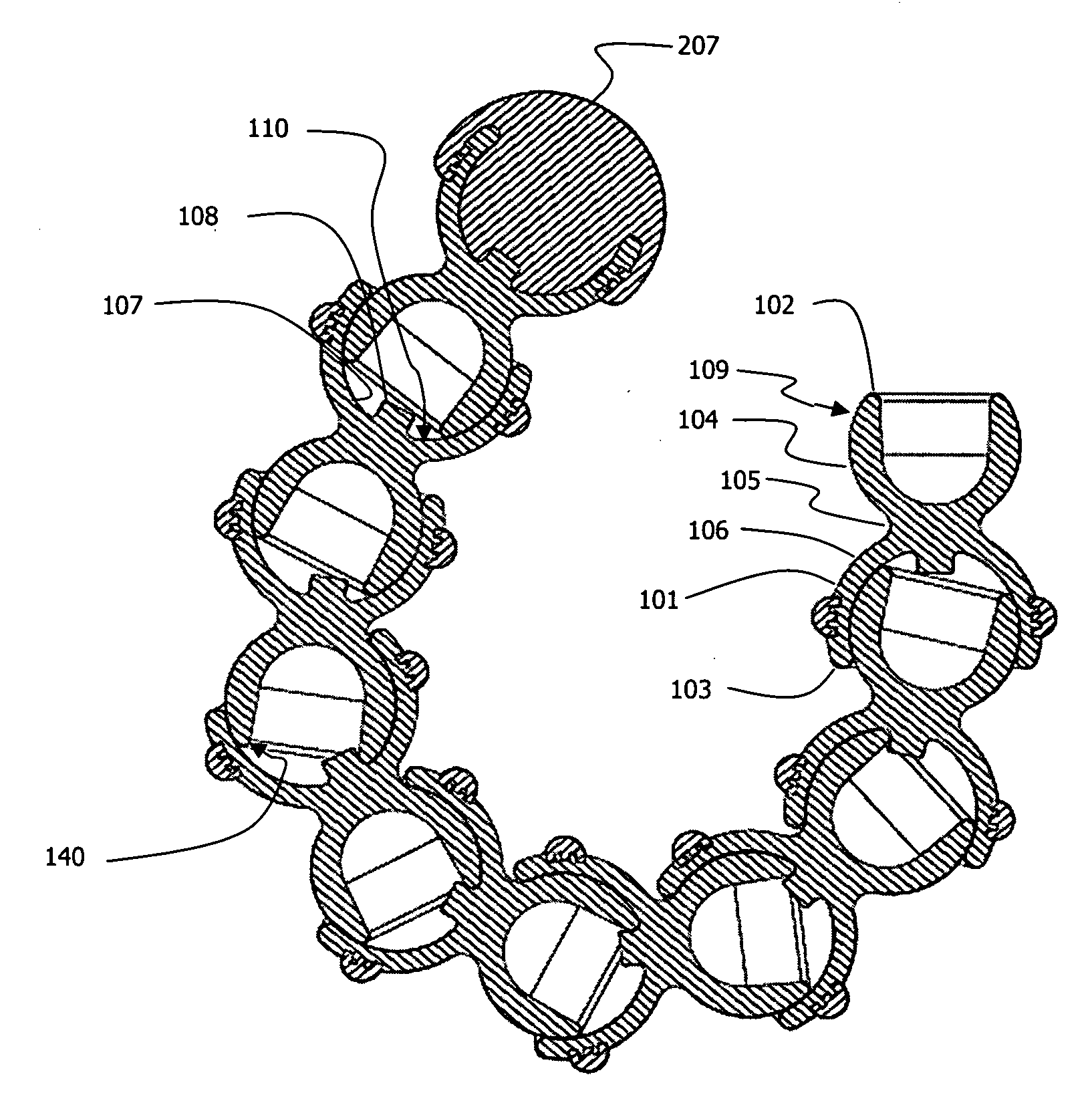
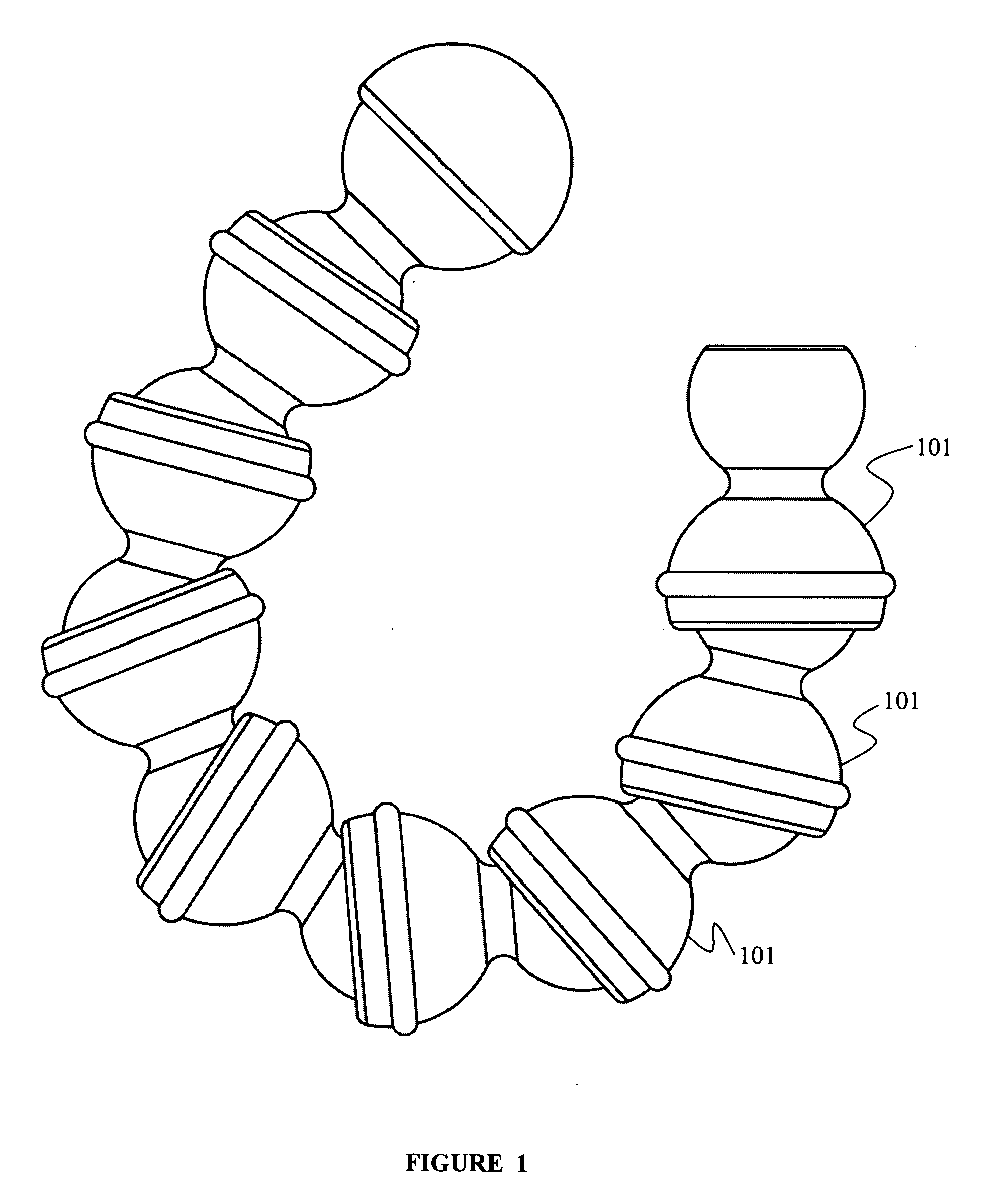
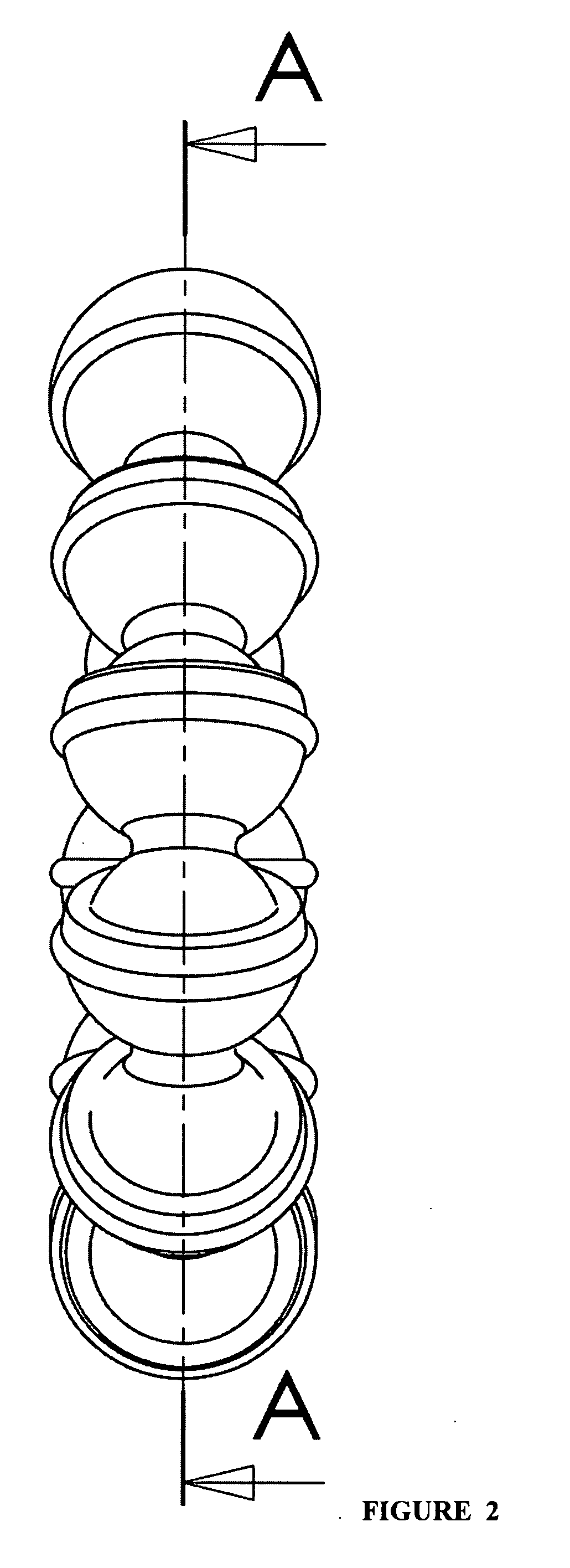
[0022]FIGS. 1, 2, and 3 illustrate a plurality of ball and socket joint connectors 101 according to some embodiments of the present invention. A connector 101 has a first end portion 102 and a second end portion 103. A socket engaging end surface 104 is present at the first end 102. The first end portion 102 is substantially hollowed out.

[0023] The second end portion 103 has a body 106 with an internal socket receiving cavity 107. The inner surface 110 of the an internal socket receiving cavity 107 is adapted to fit over the socket engaging end surface 104 of another connector 101, or of another piece with a similar socket engaging end surface. A neckdown 105 separates the first end portion 102 from the second end portion 103. A stop nub 108 acts as a mechanical stop to prevent over angulation and possible unintentional separation of a ball and socket joint connector pair.

[0024] As seen in FIG. 4, the connector 101 has a primary axis 111 in some embodiments. The connector 101 may ...


PUM


Abstract

The present invention is directed towards ball and socket joint connectors which, when interconnected, form a flexible assembly. In some embodiments, the ball and socket joint connectors are designed and constructed such that the interference fit of the ball and socket causes creep in the material resulting in more even frictions in the various ball and socket joints. In some embodiments, the ball and socket joint connectors utilize an over-molded strip around the outside of the connector to facilitate in their use for gripping. In an exemplary embodiment utilizing the aforementioned ball and socket joint connectors, a tripod apparatus uses legs comprising the ball and socket joint connectors for support and for gripping objects.

Description

BACKGROUND [0001] 1. Field of the Invention [0002] The present invention relates to connectors which interconnect into a flexible assembly, and more specifically to a mounting apparatus using ball and socket joint connectors. [0003] 2. Description of Related Art [0004] Typical tripod assemblies consist of three rigid legs which are splayed out to form a support structure for devices such as cameras. The legs are usually rigid and adapted to provide support off of the ground or other flat surface. Some tripods have some adjustment to leg length which may allow for some deviation from flatness in the surface upon which they are mounted. [0005] Such tripods are limited in the manner in which they support devices such as cameras. What is called for is a mounting apparatus that may function as a tripod and also as a grip mount for the mounting to vertical members. SUMMARY [0006] The present invention is directed towards ball and socket joint connectors which, when interconnected, form a ...

Claims


Application Information

Patent Timeline
IPC IPC(8): F16C11/06
CPCF16M11/40G03B17/56F16M11/2078F16M11/041Y10T403/32008F16M11/16F16M13/00F16M13/022Y10T403/32032F16M11/14G03B17/561F16M11/18F16C11/0661
Inventor BEVIRT, JOEBEN
Owner VIDENDUM MEDIA SOLUTIONS SPA
Learn More