
Robot cleaning system

Inactive Publication Date: 2007-07-12
SAMSUNG ELECTRONICS CO LTD
View PDF6 Cites 161 Cited by
  • Summary
  • Abstract
  • Description
  • Claims
  • Application Information

AI Technical Summary

Benefits of technology

[0012]Therefore, the invention has been made in order to solve the above problems, and it is an aspect of the invention to provide a robot cleaning system capable of performing automatic cleaning and manual cleaning with a minimal number of devices.

Problems solved by technology

Although the robot cleaner is able to reduce the labor required for manual cleaning, the robot cleaner still has several limitations.
In spite of the study, most current robot cleaners have the following several problems.
Firstly, the automatic cleaning function of the cleaning robot is limited to the floor.
The cleaning robot is not successful in automatic cleaning in other areas, for example, the surface of a sofa, shelf, or the like, and therefore, has a limited cleaning area.
Secondly, the cleaning robot is smaller than a general vacuum cleaner, and is unable to generate a strong suction force, resulting in insufficient cleaning.
A cleaning robot cannot reach all places.
Additionally, manual cleaning is preferred over a cleaning robot because a cleaning robot lacks adequate power to sufficiently clean all areas.
This results in increased costs and reduces the amount of indoor space available.

Method used


Image

  • Robot cleaning system
  • Robot cleaning system
  • Robot cleaning system

Examples


Embodiment Construction

[0032]Reference will now be made in detail to the embodiment of the invention, examples of which is illustrated in the accompanying drawings, wherein like reference numerals refer to like elements throughout. The embodiment is described below to explain the invention by referring to the figures.

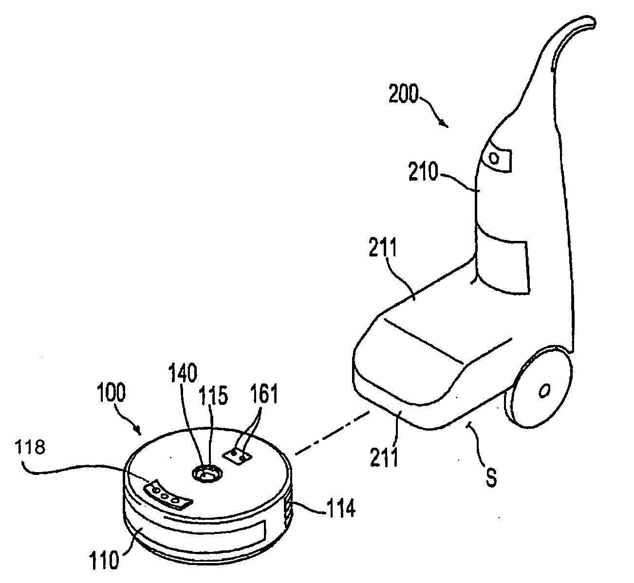
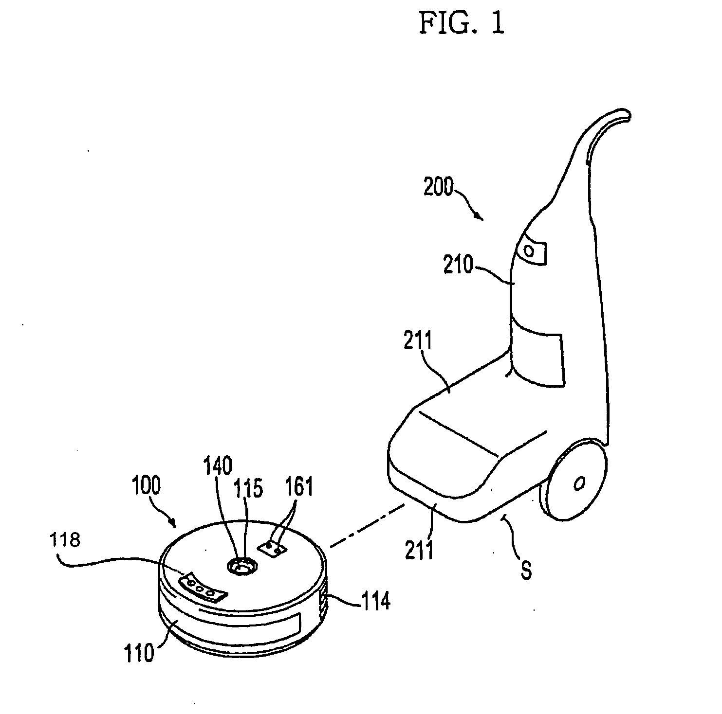
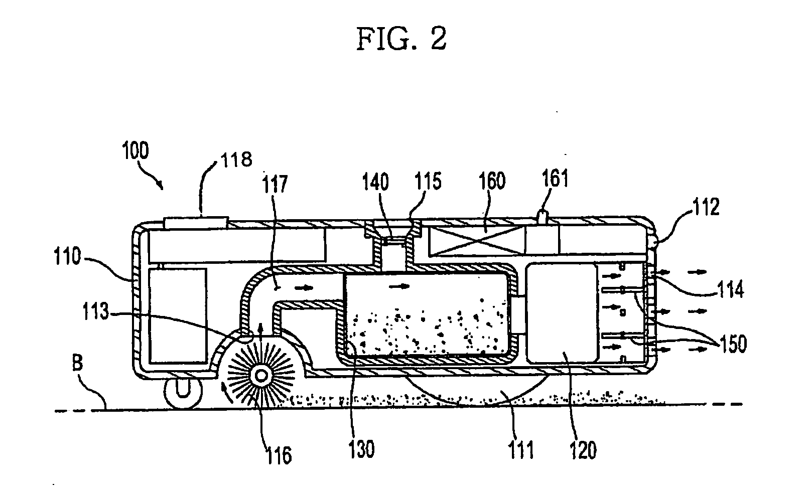
[0033]As shown in FIGS. 1 to 4, the robot cleaning system in accordance with the invention includes a first cleaning unit 100 to perform automatic cleaning while moving by itself in an area to be cleaned, and a second cleaning unit 200 to perform manual cleaning when it is coupled to the first cleaning unit 100. The first cleaning unit 100 serves as an independent robot cleaner, and the second cleaning unit 200 serves as a vacuum cleaner for manual cleaning when it is coupled to the first cleaning unit 100. When the first cleaning unit 100 is connected to the second cleaning unit 200, the second cleaning unit 200 utilizes the first cleaning unit 100 as a suction piece to vacuum dust and loose...


PUM


Abstract

A robot cleaning system is capable of performing automatic cleaning and manual cleaning with a minimal number of devices. The robot cleaning system includes a first cleaning unit to perform automatic cleaning while moving by itself in an area to be cleaned, and a second cleaning unit to perform manual cleaning while being coupled to the first cleaning unit as it is moved by a user in an area to be cleaned. Each of the first and second cleaning units contains a blower and dust collector to vacuum. The first cleaning unit has a dust outlet to deliver dust to the second cleaning unit when the first cleaning unit is coupled to the second cleaning unit via the dust outlet of the first cleaning unit, a connector, and the connection port of the second cleaning unit.

Description

CROSS-REFERENCE TO RELATED APPLICATIONS[0001]This application claims the benefit of Korean Patent Application No. 10-2006-0001922, filed on Jan. 6, 2006 in the Korean Intellectual Property Office, the disclosure of which is incorporated herein by reference.BACKGROUND OF THE INVENTION[0002]1. Field of the Invention[0003]The invention relates to a cleaner, and, more particularly, to a robot cleaning system for enabling automatic cleaning using a robot cleaner as well as manual cleaning using labor of a user.[0004]2. Description of the Related Art[0005]A cleaner is a device for cleaning the room and is typically used to remove dust, dirt, and debris in a room. Generally used is a vacuum cleaner for collecting dust and loose debris by a suction force generated from a low-pressure unit. Recently, a robot cleaner, which is designed to remove dust and loose debris from the floor while moving on the floor via self-traveling and without manual operation, has been developed. Hereinafter, the ...

Claims


Application Information

Patent Timeline
IPC IPC(8): A47L9/00
CPCA47L5/225A47L5/28A47L2201/024A47L2201/022A47L2201/00A47L9/00A47L9/20A47L9/28
Inventor LEE, JUN HWAJOO, JAE MANKWAK, JAE YOUNGSHIN, GWAN WOOWEE, HOON
Owner SAMSUNG ELECTRONICS CO LTD
Learn More