Sealed remote keyless entry device

a keyless entry device and keyless technology, applied in the direction of coupling device connections, electrical apparatus casings/cabinets/drawers, semiconductor/solid-state device details, etc., can solve the problems of design, affecting etc., to achieve the effect of improving the sealing effect of the keyless entry device, low cost assembly and small package siz

Inactive Publication Date: 2007-07-12
LEAR CORP
View PDF21 Cites 22 Cited by
  • Summary
  • Abstract
  • Description
  • Claims
  • Application Information

AI Technical Summary

Benefits of technology

[0009] The present invention has the advantage of sealing electronic components within a key fob using a corrugated seal that produces improved sealing of a keyless entry device particularly of the type used in the automotive field. The invention produces the further advantages of a small package size and a low cost assembly. A high quality tactile feel of pushbutton switches is achieved and inadvertent button activation is minimized.

Problems solved by technology

Current sealing arrangements attempt to prevent moisture from damaging the internal components of the transmitter, but they often present considerable challenges when exposed to punishing environments.
Often seal designs, however, exert forces on the housing counter to the snap retaining mechanisms.
This can result in disengagement of the housing assembly as a result of such impacts or if the housing sections are not completely engaged.
Furthermore, misalignment of the seal during assembly can exacerbate the forces on the housing sections making assembly virtually impossible without disassembly and realignment of the seal.
Considerable time and effort is often exhausted during assembly of remote keyless transmitters due to design characteristics and alignment of the seal element.

Method used


Image

  • Sealed remote keyless entry device
  • Sealed remote keyless entry device
  • Sealed remote keyless entry device

Examples


Embodiment Construction

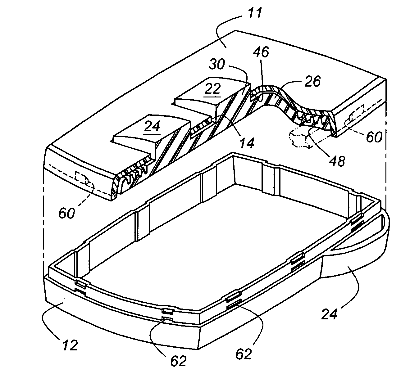
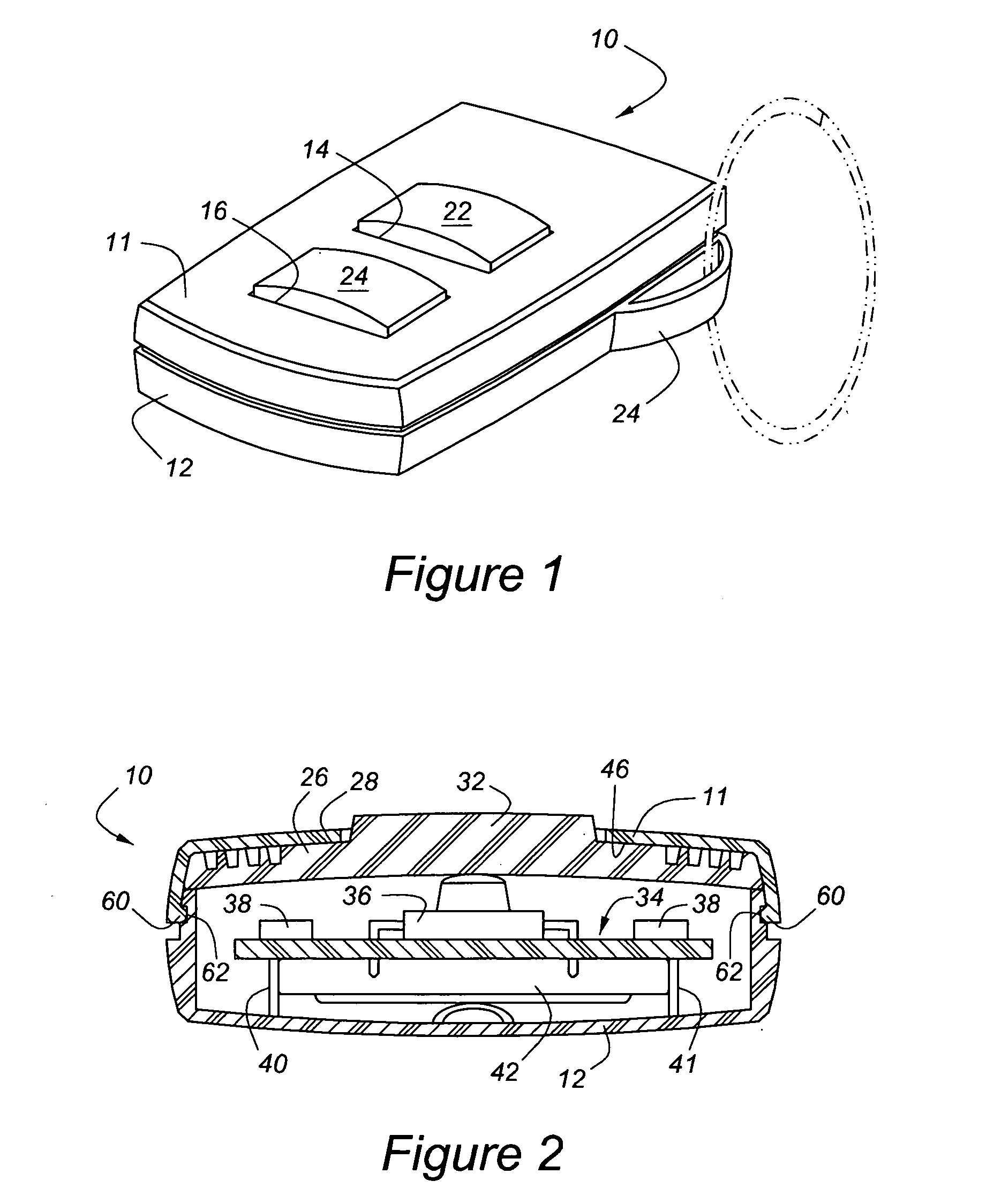
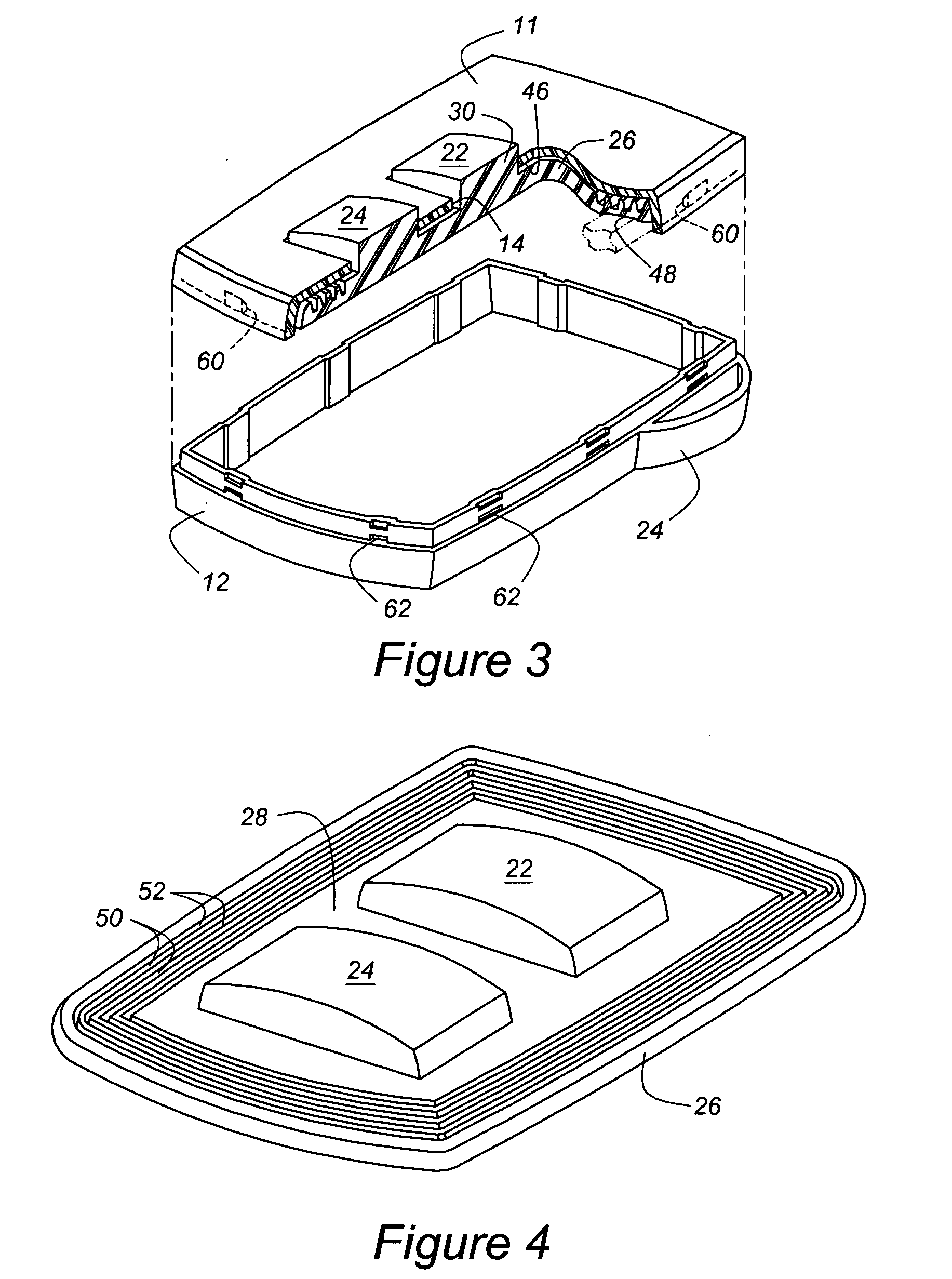
[0017] Referring now to FIGS. 1 and 2, the remote keyless entry device (RKE) or RKE device 10 includes a front casing member 11 and a rear casing member 12 enclosing RKE device electronics. Front casing member 11 includes a plurality of button apertures 14, 16 for receiving button caps 20, 22, respectively. The button caps 20, 22 may be imprinted with graphic symbols to identify various commands to be transmitted to the vehicle or for adjusting functions within the RKE device 10. Front and rear casing members 11, 12 cooperatively form a key ring passage 24. An elastomeric seal member 26 is located between the front and rear casing members 11, 12. Preferably, seal member 26 does not extend into the key ring passage 24.

[0018]FIGS. 2 and 3 show RKE device 10 in cross section to reveal the seal member 26 in greater detail. The seal member 26, which is preferably formed of compression-molded silicone and molded integrally as a unit, includes a plurality of pedestals that extend locally ...


PUM


Abstract

A keyless entry device includes a rear casing having a first surface extending along a periphery of the rear casing member, an electronic circuit located in the rear casing member and including comprising a substrate and switching elements supported on the substrate, a front casing including a second surface facing the first surface and extending along a periphery of the rear casing member having button apertures aligned with a switching element. A seal element of compressible elastic material includes a peripheral flange comprising multiple protrusions located between the first surface and the second surface, the protrusions producing elastic preloaded contact between the front and rear casing members when the device is assembled, and pedestals aligned with a button aperture and a switching element. Button caps are aligned with a button aperture and located above one of the pedestals.

Description

BACKGROUND OF THE INVENTION [0001] The present invention relates generally to an automotive remote keyless entry device housing and elastomer seal assembly and more specifically to an automotive remote keyless entry device assembly with improved seal integrity and improved assembly durability. [0002] Wireless remote control units for use with motor vehicles are well known in the art. One typical type of system includes a remote keyless entry system for remotely locking and unlocking doors and performing other functions. The wireless communication system comprises a vehicle-mounted receiver and a portable key fob carried by the user. The key fob contains various push buttons for initiating the transmission of particular remote control commands (e.g., lock doors, unlock doors, unlock trunk, or initiate panic alarm). [0003] Key fobs are being increasing deployed for applications using two-way communication between the key fob and the vehicle. Two-way communication is utilized, for exam...

Claims


Application Information

Patent Timeline
Patent Type & Authority Applications(United States)
IPC IPC(8): H02G3/14
CPCG07C2009/00984H01H9/0235H05K5/061H01H2223/003H01H13/86G07C9/00944H04Q9/00
Inventor BURCA, JOHNBUCCINNA, FRANK
Owner LEAR CORP
Why Eureka
Try Eureka