Rotational shearing filter

a technology of rotating shearing filter and rotating shearing blade, which is applied in the direction of gravity filter, loose filtering material filter, mixer, etc., can solve the problem of immediate destruction and achieve the effect of optimal use of spa

Inactive Publication Date: 2007-07-12
ANDREAS KUFFERATH
View PDF7 Cites 2 Cited by
  • Summary
  • Abstract
  • Description
  • Claims
  • Application Information

AI Technical Summary

Benefits of technology

[0003] The object of the present invention is to contrive a rotational shearing filter such that regardless of the material selection, and thus regardless of the thermal expansion behavior of the drive shaft and housing, there is no risk of the shearing elements and the filter disks coming into contact with one another. This is also to be the case when the distances between the shearing elements and the filter disks are selected to be particularly small in order to assure optimum use of space.

Problems solved by technology

For proper operating, it is necessary that the shearing elements that act as stirrers never touch the filter disks, because this would lead to immediate destruction of the latter.

Method used


Image

  • Rotational shearing filter
  • Rotational shearing filter
  • Rotational shearing filter

Examples


Embodiment Construction

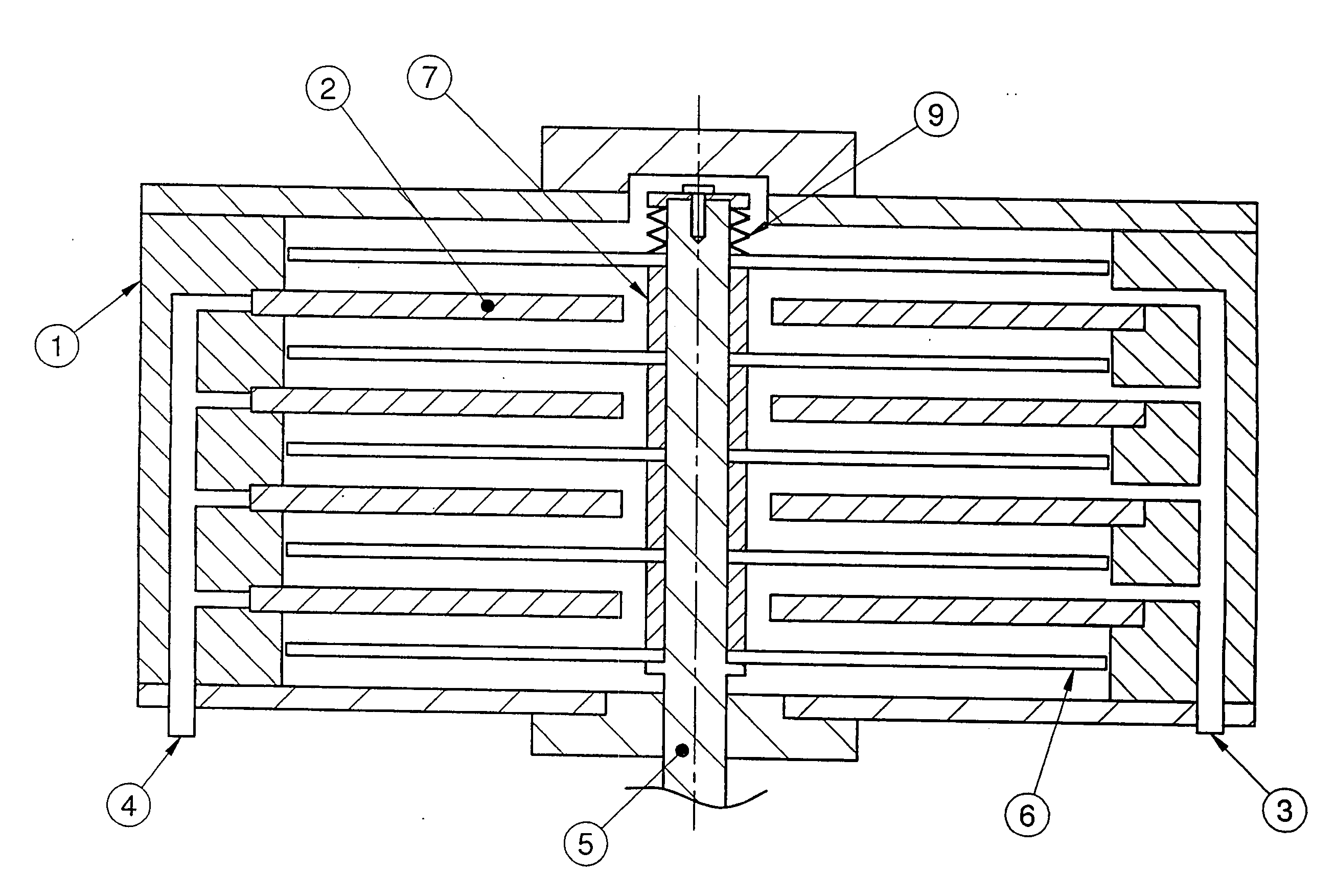
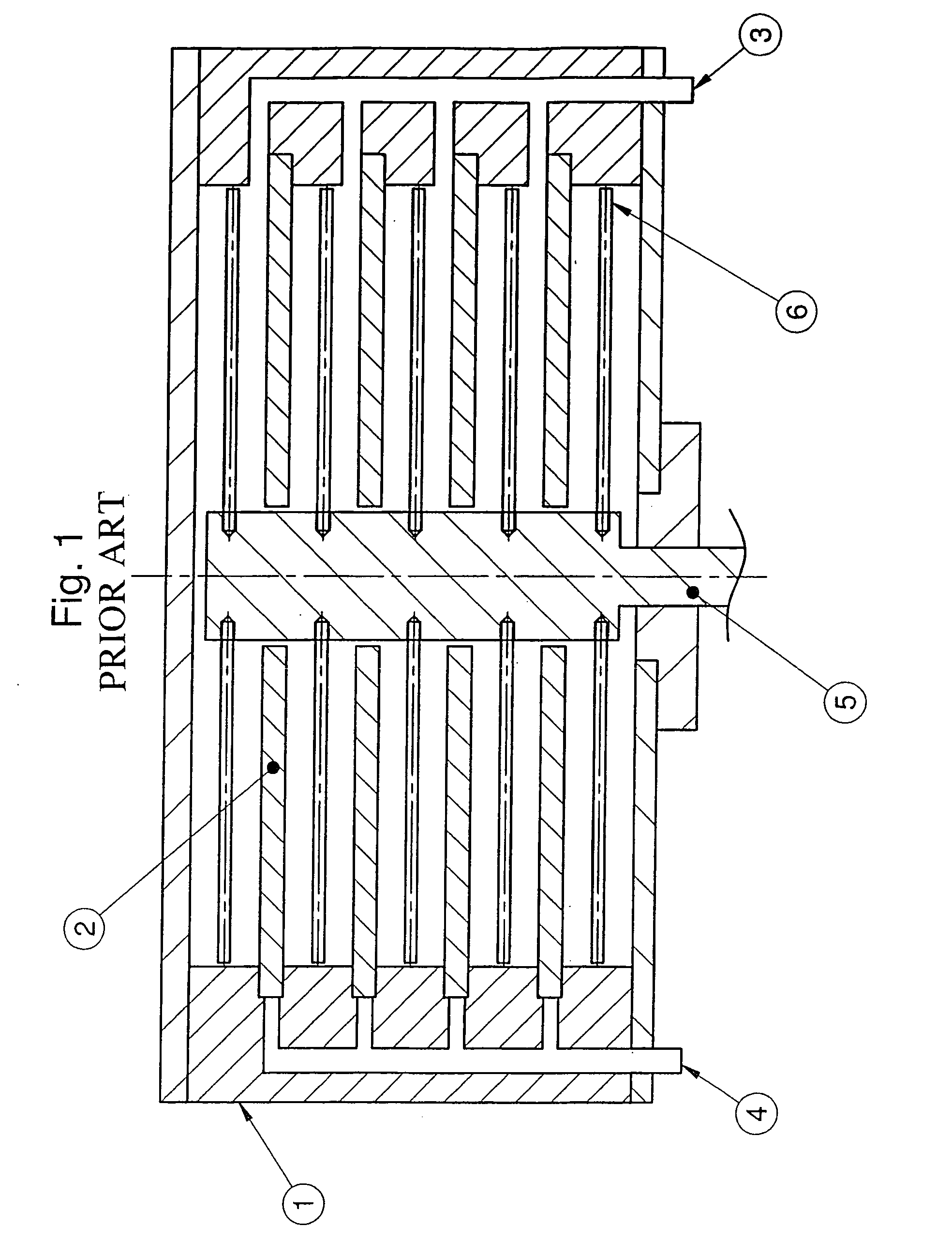
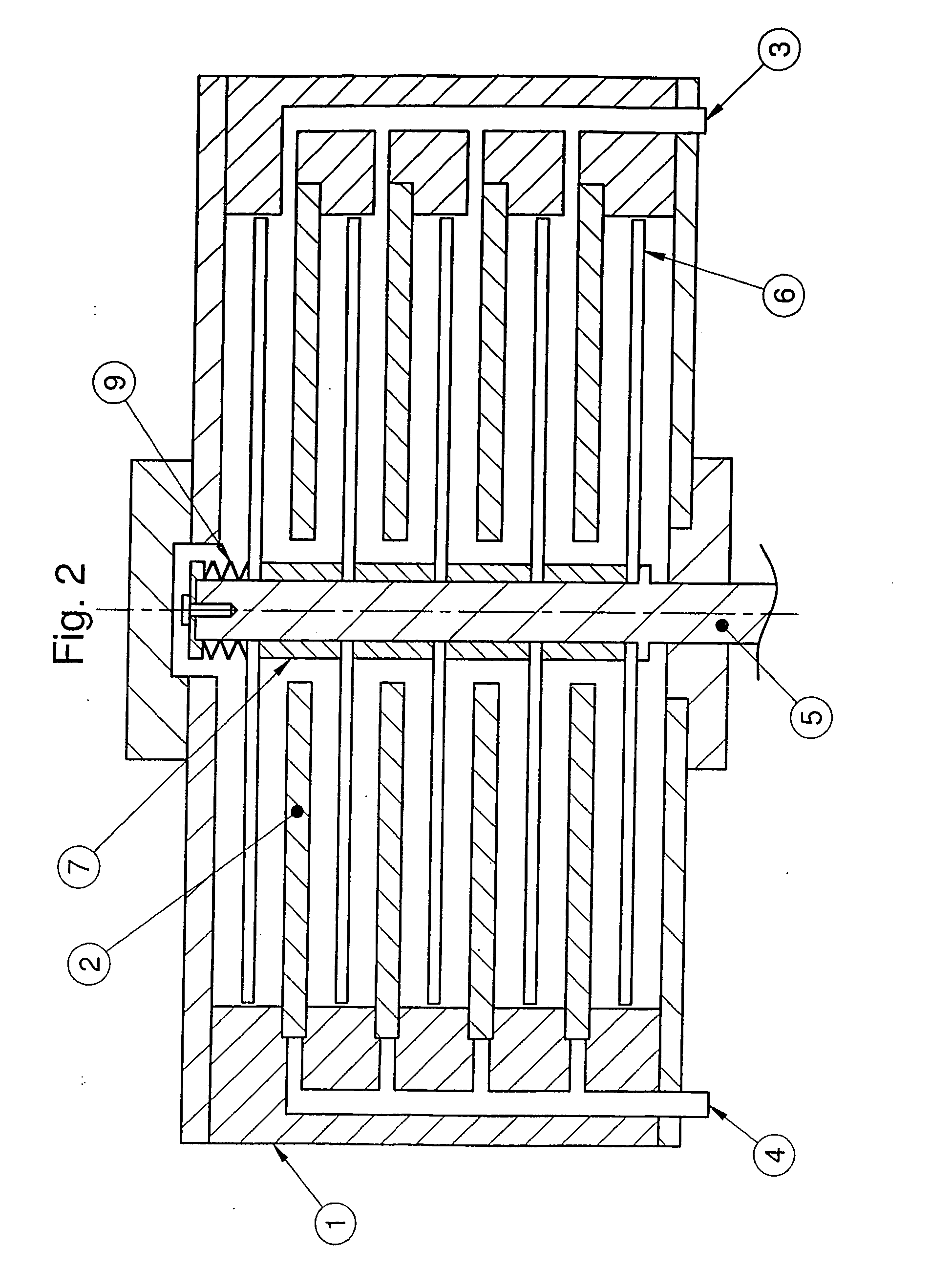
[0013] In a known rotational shearing filter in accordance with FIG. 1, a plurality of annular hollow filter disks 2 are arranged spaced apart in a cylindrical metallic housing 1 and held in annular receiving depressions of the housing 1. A suspension for filtering can be introduced into the interior housing areas between the filter disks 2 via a branching suspension inlet 3 embodied in the housing 1. From there the liquid components of the suspension can flow into the interior of the filter disks 2 in a filtered manner and then flow out via a branched filtrate outlet 4 embodied in the housing 1. A housing outlet (not shown) corresponding to the suspension inlet 3 drains the viscous medium enriched with solids out of the housing 1.

[0014] In order to prevent loading of the filter disks 2, during operation their surfaces are passed over in a contactless manner by shearing elements 6 that are inserted between the filter disks 2 and that are attached to a rotatably driven central drive...


PUM

PropertyMeasurementUnit
coefficient of heat expansionaaaaaaaaaa
coefficients of thermal expansionaaaaaaaaaa
permeabilityaaaaaaaaaa

Abstract

A rotational shearing filter is disclosed which includes a housing and several spaced-apart, stationary, coaxial, annular, hollow filter disks that are disposed therein. Several shearing elements are retained in a torsion-proof manner on a central, rotatable drive shaft which penetrates the filter disks. The shearing elements are placed next to the annular surfaces of the filter disks, which point in the axial direction of the housing, so as to keep the filter disks penetrable for filtrate that penetrates from the housing into the filter disks. In order to prevent the shearing elements and the filter elements from touching each other as a result of thermal expansion, the shearing elements that are connected to the drive shaft so as to rotate therewith are guided thereon in an axially movable manner while spacers which axially displace the shearing elements according to longitudinal modifications of the housing occurring due to thermal conditions are positioned between the shearing elements. The spacers can be arranged directly between adjacent shearing elements and can be made of a material corresponding to the thermal expansion behavior of the housing. Alternatively, the spacers can be made of a largely random material while limiting the minimum distances between the shearing elements and the filter disks or the facing housing walls.

Description

BACKGROUND OF THE INVENTION [0001] The invention relates to a rotational shearing filter having a housing and a plurality of spaced-apart, coaxial, annular, hollow filter disks arranged therein, whereby held rotationally fast on a rotatable central drive shaft that penetrates the filter disks are a plurality of shearing elements that are adjacent to the annular surfaces of the filter disks in the axial direction of the housing for maintaining their filter permeability for filtrate that penetrates out of the housing into the filter disks. [0002] For proper operating, it is necessary that the shearing elements that act as stirrers never touch the filter disks, because this would lead to immediate destruction of the latter. The drive shaft must be able to absorb forces that occur during operation and must never bow appreciably. For this reason the drive shaft generally comprises metal such as for instance steel or high-grade steel. The drive shaft and the filter disks must have very si...

Claims


Application Information

Patent Timeline
Patent Type & Authority Applications(United States)
IPC IPC(8): B01D35/16B01D29/05B01F27/93
CPCB01D29/055B01D29/39B01D29/54B01D29/86
Inventor MAUER, GREGOR
Owner ANDREAS KUFFERATH
Why Eureka
Try Eureka