Static pierce point centering spring seat

Inactive Publication Date: 2007-07-12
ARVINMERITOR TECH
View PDF8 Cites 9 Cited by
  • Summary
  • Abstract
  • Description
  • Claims
  • Application Information

AI Technical Summary

Benefits of technology

[0007] A shock absorber assembly includes a two-piece spring seat that allows pre-vehicle installation adjustment to achieve a desired spring pierce point location for a select

Problems solved by technology

Side loads generated by the coil spring can cause wear and increased levels of friction between the rod and associated cylinder bearings and seals.
This can lead to premature failure of the shock absorber assembly.
However, the coil ends are typically provided with non-parallel coil end planes, which results in dynamically varying spring pierce points.
The

Method used


Image

  • Static pierce point centering spring seat
  • Static pierce point centering spring seat
  • Static pierce point centering spring seat

Examples


Embodiment Construction

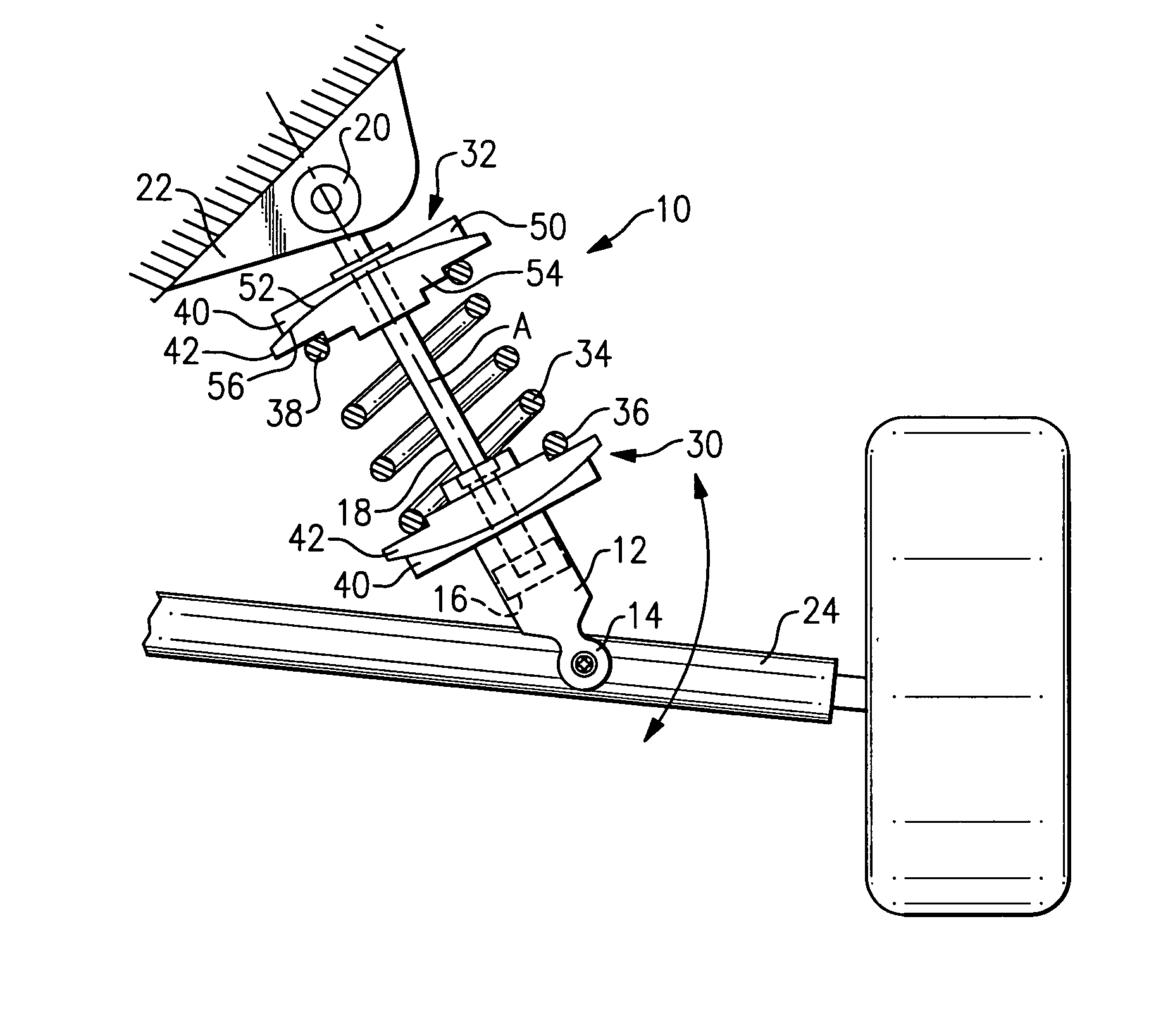
[0020]FIG. 1 shows a shock absorber 10 including a cylinder 12 with a first mount 14, a piston 16 received within the cylinder 12, and a rod 18 coupled to the piston 16. The rod 18 defines an axis A that extends along a length of the rod 18. The rod 18 moves the piston 16 back and forth within the cylinder 12 along the axis to compensate for road load inputs as known.

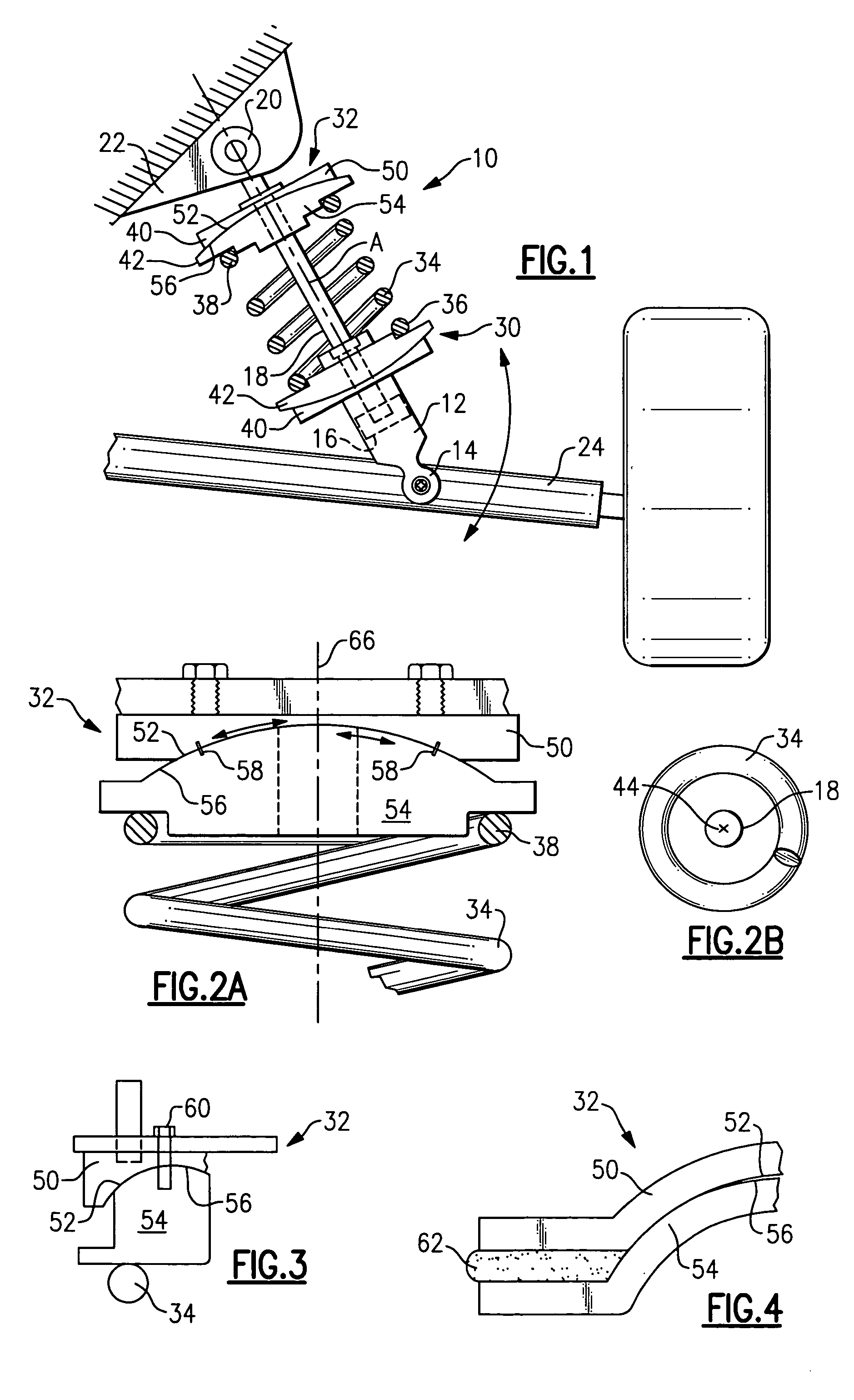
[0021] A second mount 20 is attached to the rod 18. The second mount 20 is attached to a vehicle structure 22, such as a frame or chassis member for example. The first mount 14 is attached to a wheel structure 24, such as control arm for example. A reverse orientation could also be used with the first mount 14 being attached to the vehicle structure 22 and the second mount 20 being attached to the wheel structure 24. Further, the first 14 and second 20 mounts can be pivoting mounts as shown in FIG. 1, or could be a fixed mount such as that shown in FIG. 2A.

[0022] A first spring seat 30 is fixed to the cylinder 12. A s...


PUM


Abstract

A shock absorber assembly includes a coil spring that reacts between first and second spring seats. The first spring seat is fixed to a shock cylinder and the second spring support is fixed to a rod that is slidably received within the shock cylinder. At least one of the first and second spring seats comprises an adjustable two-pierce spring seat. First and second spring seat pieces are initially movable relative to each other to achieve a desired spring pierce point location for a selected operational position. Once the first and second spring seat pieces are adjusted to a desired position, the first and second spring seat pieces are permanently attached to each other.

Description

TECHNICAL FIELD [0001] A shock absorber assembly includes an adjustable two-piece spring seat that is used to set a spring pierce point at a desired location prior to installation in a vehicle. BACKGROUND OF THE INVENTION [0002] Shock absorber assemblies react between a vehicle frame and vehicle wheel to reduce vibration and shock load inputs to improve ride comfort. A typical shock absorber assembly includes a cylinder that slidably receives a piston coupled to a rod. One end of the rod is mounted to the vehicle frame and the cylinder is mounted to a vehicle wheel structure. A coil spring reacts between a first spring seat on the cylinder and a second spring seat on the rod. [0003] Side loads generated by the coil spring can cause wear and increased levels of friction between the rod and associated cylinder bearings and seals. This can lead to premature failure of the shock absorber assembly. [0004] It is preferred to maintain a center of load, i.e. spring pierce point, to be gener...

Claims


Application Information

Patent Timeline
IPC IPC(8): B60G15/00F16F1/12B60G11/14
CPCB60G11/16B60G2202/12B60G2204/124F16F1/126B60G2204/1244B60G2204/416B60G2204/4232B60G2204/1242
Inventor FADER, JOSEPH A.SMITH, MARK CHRISTOPHERMISKA, PAUL KURTSALIM, MUHAMMADHEAGLE, STEPHENSENDREA, DARRYLCLARK, NATHANMOEN, EVAN ROGER
Owner ARVINMERITOR TECH
Why Eureka
Try Eureka