
Camera module whose lens and image sensor can be easily positioned relative to each other

Inactive Publication Date: 2007-07-12
ALPS ALPINE CO LTD
View PDF10 Cites 14 Cited by
  • Summary
  • Abstract
  • Description
  • Claims
  • Application Information

AI Technical Summary

Benefits of technology

[0006]The present invention is made in view of the above problems, and an object of the present invention is to provide a small camera module that does not need a mechanism for adjustment and whose lens and image sensor can be easily positioned relative to each other.
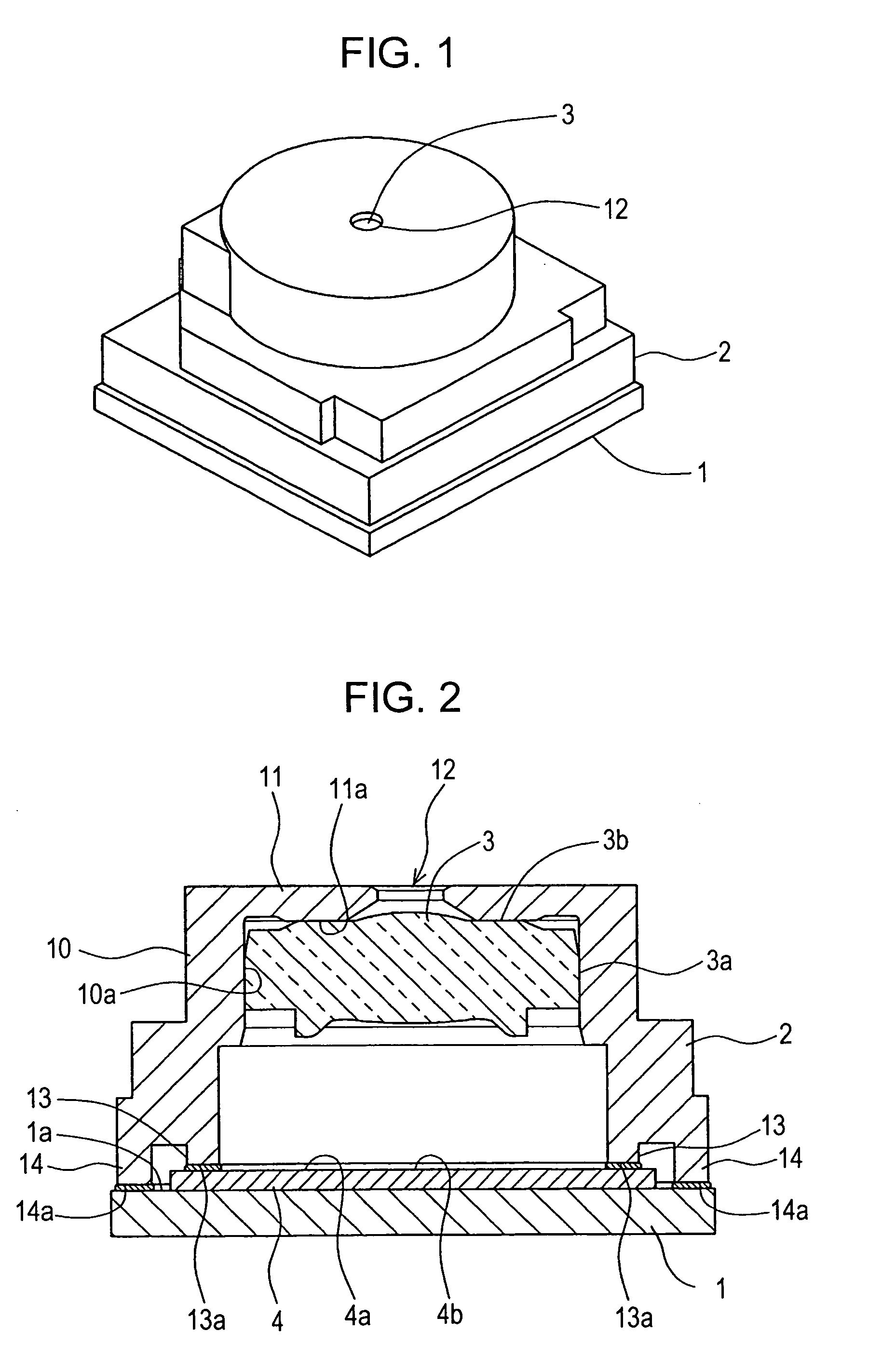
[0011]The camera module according to the present invention integrally has a protrusion that protrudes toward an image sensor and an outer peripheral portion provided outside the protrusion, the lower end of the outer peripheral portion is lower than the lower end of the protrusion. The lower end surface of the protrusion is fixed to the upper surface of the image sensor with an adhesive. The lower end surface of the outer peripheral portion is fixed to the upper surface of the substrate with an adhesive. By controlling the amount of the adhesive between the holder and the image sensor and controlling the pressure applied during the adhesion, the thickness of the adhesive between the holder and the image sensor can be set in advance, and an appropriate distance between the lens and the image sensor can be easily and accurately achieved without adjustment. In addition, by fixing the outer peripheral portion to the substrate with an adhesive, a sufficient fixing strength can be ensured even if the camera is small, and both the cost and the size can be reduced.
[0012]Moreover, in the camera module according to the present invention, the holder has a top plate formed integrally therewith just above the image sensor. The top plate has an opening that functions as an optical stop. Therefore, it is not necessary to provide a component that functions as a stop. Since the number of components can be reduced, the cost can be reduced.
[0013]Furthermore, in the camera module according to the present invention, the outer peripheral surface of the lens is in contact with and fixed by adhesion to the inner peripheral surface of the holder or the lens barrel. Since the adhesive does not affect the position of the lens in the vertical direction, an accurate positional relationship between the lens and the image sensor can be achieved.

Problems solved by technology

In addition, an increased number of manufacturing processes increases the cost.

Method used


Image

  • Camera module whose lens and image sensor can be easily positioned relative to each other
  • Camera module whose lens and image sensor can be easily positioned relative to each other
  • Camera module whose lens and image sensor can be easily positioned relative to each other

Examples


first embodiment

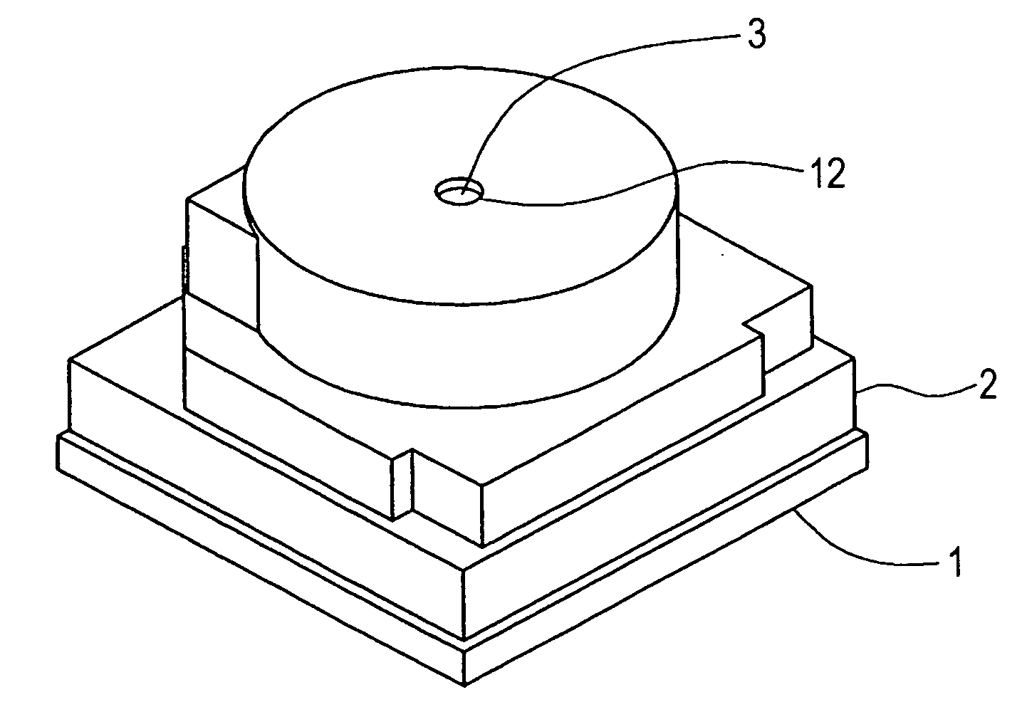
[0017]The embodiments of the present invention will now be described with reference to the drawings in detail. FIG. 1 is a perspective view of a camera module manufactured using a method according to a FIG. 2 is a sectional view of the camera module. As shown in FIG. 1, this camera module includes a substrate 1 and a holder 2 disposed thereon. The holder 2 has an integral structure. The holder 2 has an opening 12 formed in the upper surface thereof. The holder 2 holds a lens 3 therein. The lens 3 is coated with a film that functions as a filter to block infrared.

[0018]As shown in FIG. 2, an image sensor 4 is disposed on the upper surface 1a of the substrate 1. The image sensor 4 has a light receiving section 4b in the central part thereof. The image sensor 4 has a large number of photoelectric conversion elements arrayed on a plane. The image sensor 4 converts light collected by the lens 3 into image data and outputs the image data. The image sensor 4 is slightly smaller than the s...

second embodiment

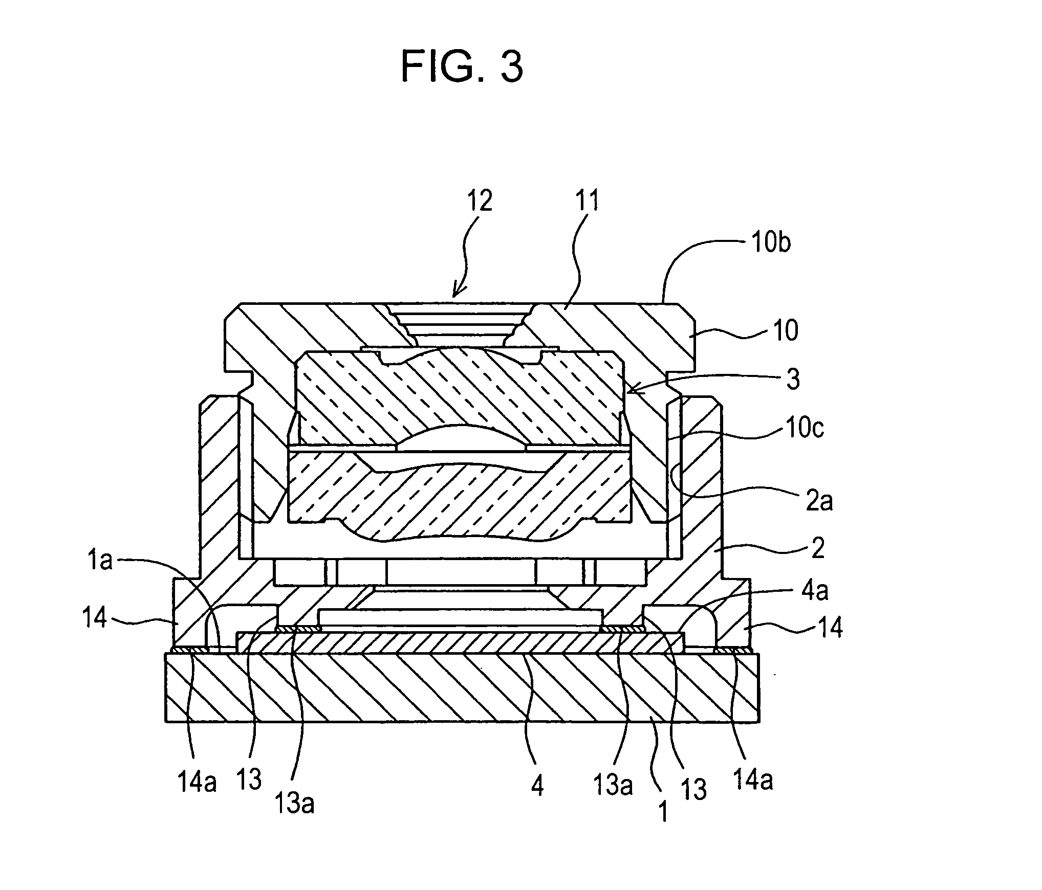
[0023]Next, the present invention will be described. FIG. 3 is a sectional view of a camera module according to this embodiment. In the camera module, a lens barrel 10 that holds a lens 3 therein and a holder 2 are separate components. The upper portion of the holder 2 is hollow cylindrical so as to be able to hold the lens barrel 10 therein. The inner peripheral surface 2a of the holder 2 is provided with a screw thread. The outer peripheral surface 10c of the lens barrel 10 is provided with a screw thread corresponding to the screw thread of the holder 2. The lens barrel 10 has a top plate 11 provided at the top thereof. In addition, the lens barrel 10 has a flange 10b protruding from the outer peripheral surface 10c thereof.

[0024]In the second embodiment, the lens barrel 10 can be optically adjusted by being rotated relative to the holder 2. Although the cost of adjustment cannot be reduced, the holder 2 can be stably fixed in aspects of size and strength, in a small camera, with...


PUM


Abstract

A camera module includes a lens held in a cylindrical holder and an image sensor disposed at a predetermined distance from the lens. The image sensor is disposed on a substrate. The holder integrally has a protrusion that protrudes toward the image sensor and an outer peripheral portion provided outside the protrusion, the lower end of the outer peripheral portion being lower than the lower end of the protrusion. The lower end surface of the protrusion is fixed to the upper surface of the image sensor with an adhesive, and the lower end surface of the outer peripheral portion is fixed to the upper surface of the substrate with an adhesive.

Description

BACKGROUND OF THE INVENTION[0001]1. Field of the Invention[0002]The present invention relates to a camera module including a lens and an image sensor, and more specifically, it relates to a camera module in which positioning of a holder relative to a substrate is performed using an adhesive.[0003]2. Description of the Related Art[0004]A camera module provided in small electronic devices such as cell-phones at least includes a lens, a lens barrel holding the lens, and an image sensor that converts light collected by the lens into an electric signal. The distance between the lens and the image sensor is important for obtaining an excellent image in the image sensor. Therefore, the mounting position of the lens barrel relative to the main body is adjusted on a camera-module by camera-module basis. The distance between the lens in the lens barrel and the image sensor can be appropriately adjusted by threading the inner peripheral surface of the main body and the outer peripheral surface...

Claims


Application Information

Patent Timeline
IPC IPC(8): G03B17/00G02B7/02H01L27/14H04N5/225H04N5/335
CPCG02B13/0015G02B13/0025G02B13/003H04N5/2257G03B17/28H04N5/2251G03B7/099H04N23/57H04N23/55
Inventor KIKUCHI, KIMIHIROINOUE, YOSHITAKAWADA, SATOSHI
Owner ALPS ALPINE CO LTD
Learn More