
Portable toilet

a portable toilet and toilet technology, applied in the field of portable restrooms, can solve the problems of affecting the overall feeling of use of the portable restroom, affecting the comfort of users, and overwhelming any existing restroom facilities, and achieve the effect of increasing the comfort of users

Inactive Publication Date: 2007-07-19
SATELLITE IND
View PDF2 Cites 9 Cited by
  • Summary
  • Abstract
  • Description
  • Claims
  • Application Information

AI Technical Summary

Benefits of technology

[0008] In light of the complications outlined above, the present invention provides a portable restroom which has increased comfort for the user. More particularly, the present invention provides these comforts in part through the unique design of its base structure. This unique design provides two primary features that are incorporated into a single design. First, a dual water tank system is provided which effectively utilizes space contained within the runners of the base unit to provide flushing water to the portable restroom. More significantly, this dual tank capability is made feasible through the use of unique siphoning pump which draws water from each tank uniformly, while also having a self-leveling feature.
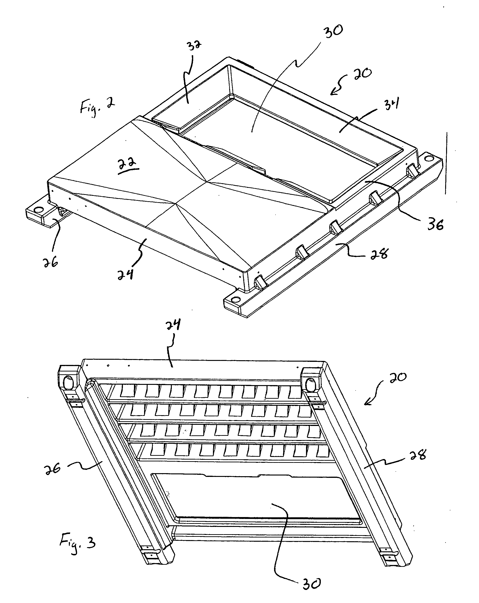
[0009] Secondly, the base unit of the present invention includes a ribbing structure, in a roto-molded product, which provides additional rigidity and strength to the floor. Consequently, when users enter the portable restroom of the present invention, the floor itself is rigid and solid feeling, thus providing a certain level of comfort to the user. This rigidity is achieved through an alternating structure of arched ribs, which bridge between pairs of primary beams in the floor structure itself. Consequently, the support points are evenly distributed throughout the floor resulting in a structure which more easily handles the desired loads. Additionally, the design is more easily fabricated using the desired roto-molding process because the material being molded efficiently fills the desired design. While the design itself provides additional support for the floor, the component functions much more efficiently (due to better formation when molded).

Problems solved by technology

In each of these applications, large groups of people are expected to attend, thus being overwhelming to any existing restroom facilities.
When this occurs, immediate feedback is provided to the user, suggesting that the restroom is not extremely strong or rigid, thus inherently affecting their feeling of comfort.
In addition to the desired comfort and security, other features also affect the user's overall feeling of using portable restrooms.
Naturally, adding these features or functions requires additional systems within the portable restroom, which complicates the overall product and adds to the cost / complexity involved in manufacturing.
That said, complications do exist related to the formation of a water holding tank within the base.
Specifically, it is difficult to create a single tank which has inner-connected water ways and effectively utilizes all of the available area within the base unit.
Further, when the portable restroom is utilized in unleveled locations, this single flushing tank becomes very problematic as available water will naturally migrate to a single side or edge of the base reservoir.
Consequently, this single reservoir within the base unit is not completely ideal for all applications.

Method used


Image

  • Portable toilet
  • Portable toilet
  • Portable toilet

Examples


Embodiment Construction

[0023] Certain features of the present invention are described below with regards to a preferred embodiment, as illustrated in the attached figures. Naturally, it will be understood by those skilled in the art, that certain variations and modifications could be made to this structure, without departing from the scope and spirit of the present invention.

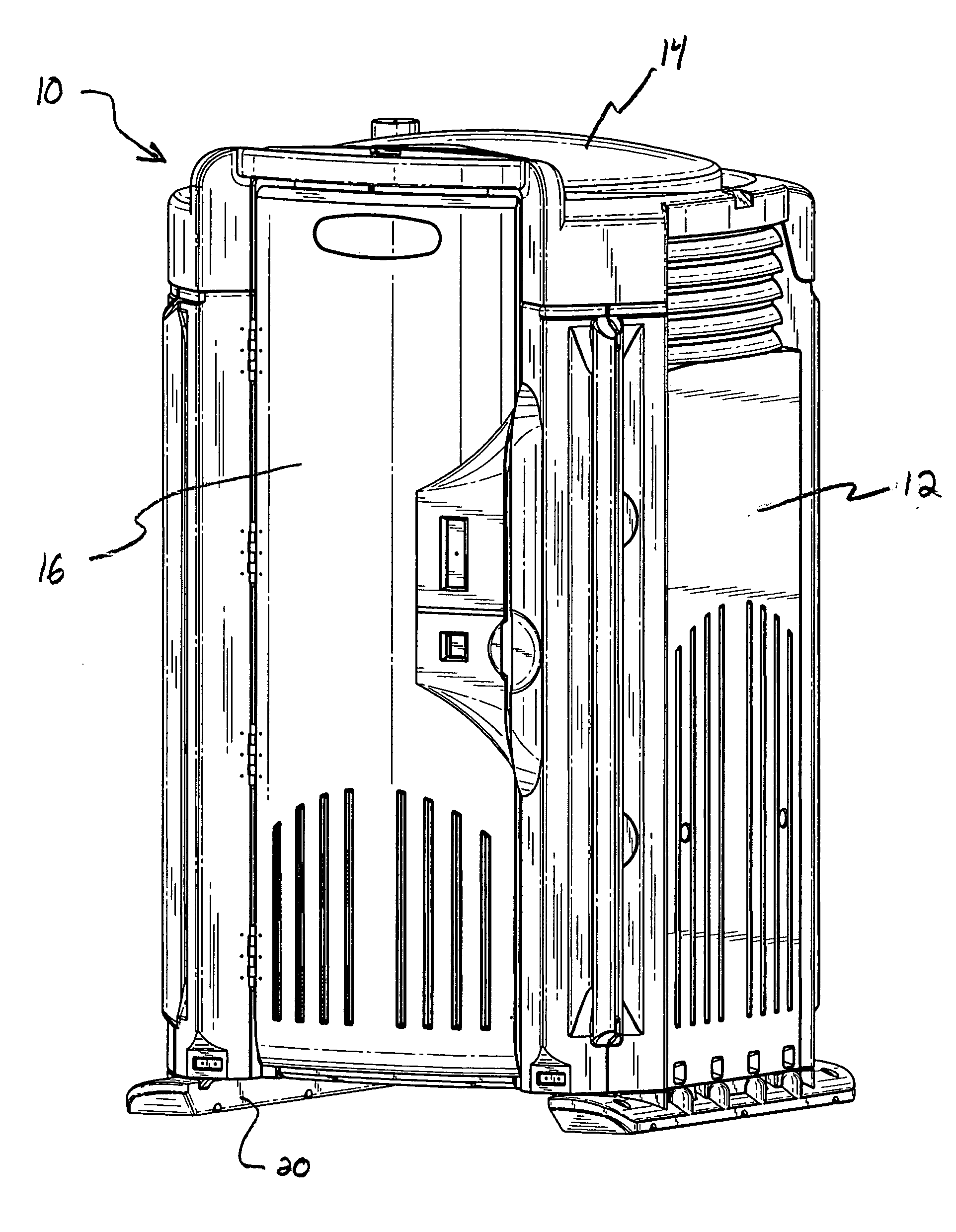
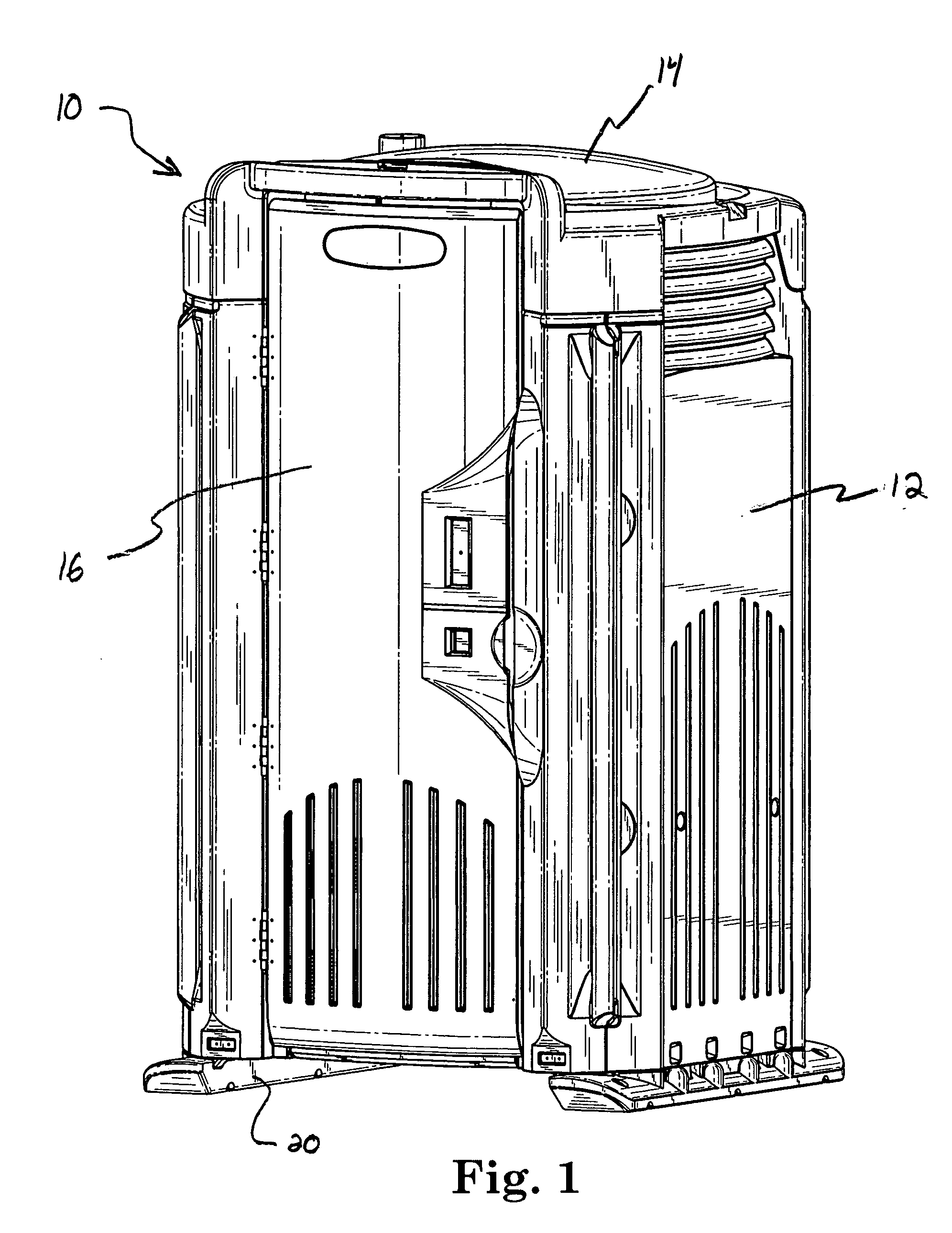
[0024] Referring now to FIG. 1, there is shown a perspective view of one embodiment of a portable restroom 10, having a restroom base 20, a plurality of exterior walls 12, a roof 14 and an enclosure door 16, all combined to create an enclosure for the portable restroom. Naturally, additional structures are contained within this enclosure to provide the necessary features, including a toilet structure having a waste tank of some type, potentially a urinal, appropriate tank venting, and air flow mechanisms (each of these features not shown in FIG. 1).

[0025] Referring now to FIGS. 2 and 3, perspective views of the restroom base 20 are ...


PUM


Abstract

A portable restroom is designed to provide features which enhance the comfort and appeal to users. These features include a rigid and stable structure, including a rigid floor structure, thus providing a sense of security to the user. Further, flushing and fresh water capabilities are achieved by using a dual tank structure made capable by the base design itself. This dual tank structure is achieved utilizing a unique siphoning pump to provide appropriate functionality.

Description

CROSS REFERENCE TO RELATED APPLICATIONS [0001] This application claims the benefit of U.S. Provisional Application No. 60 / 724,557, filed Oct. 8, 2005.BACKGROUND OF THE INVENTION [0002] The present invention relates to a portable restroom. More specifically, the present invention relates to the floor structure of a portable restroom which includes unique supports to provide a more rigid floor, and which includes a unique water tank feature which provides a flushing capability for the restroom. [0003] Portable restrooms are a widely used and very convenient part of today's society, providing facilities at many different locations when necessary. For example, these portable restrooms are often used at public events such as sporting events, outdoor concerts, public meetings, etc. In each of these applications, large groups of people are expected to attend, thus being overwhelming to any existing restroom facilities. [0004] While the public clearly understands that the portable restrooms...

Claims


Application Information

Patent Timeline
IPC IPC(8): A47K11/02
CPCB65D2519/00412E04H1/1216
Inventor HOLMSTADT, RONALD J.
Owner SATELLITE IND
Learn More