
Method and apparatus for transverse distribution of a flowing medium

a technology of transverse distribution and flowing medium, applied in the direction of papermaking, textiles and paper, machine wet end, etc., can solve the problems of poor efficiency, difficult to predict the variation in velocity along individual streamlines of flowing medium, and poor pulp quality

Inactive Publication Date: 2007-07-19
VALMET TECH INC
View PDF13 Cites 0 Cited by
  • Summary
  • Abstract
  • Description
  • Claims
  • Application Information

AI Technical Summary

Benefits of technology

[0021] After passage through the gaps, the flowing medium passes an outlet opening. Preferably, the outlet opening is preceded by several distribution gaps having different column depths for the purpose of controlling frictional losses in different parts of the machine.
[0023] By “frictional surface” in this description is meant those surfaces with which the flowing medium is in contact. It is the quantity of frictional surface in the distribution gap, alternatively the distribution gaps, and not the outlet gap, that controls the profile of the flow. The shape of the edge may compensate for frictional losses in the outlet gap.

Problems solved by technology

An uneven formation may thus result in an impaired pulp quality, for example due to fiber damages at subsequent press nips in thicker formed sections, canalization of the washing liquid, and poor efficiency during displacement washing.
One problem in applying the first principle (1) above is that the variation in velocity along individual streamlines of the flowing medium is hard to predict.
This fact in combination with limited knowledge about the boundary layer behavior of e.g. suspensions of wood fibers, makes it difficult to predict the pressure drop along the streamlines.
One problem is clogging of the distributor when the fibers tend to slow down or adhere to the inner faces of the distributor which influences the runnability.

Method used


Image

  • Method and apparatus for transverse distribution of a flowing medium
  • Method and apparatus for transverse distribution of a flowing medium
  • Method and apparatus for transverse distribution of a flowing medium

Examples


Embodiment Construction

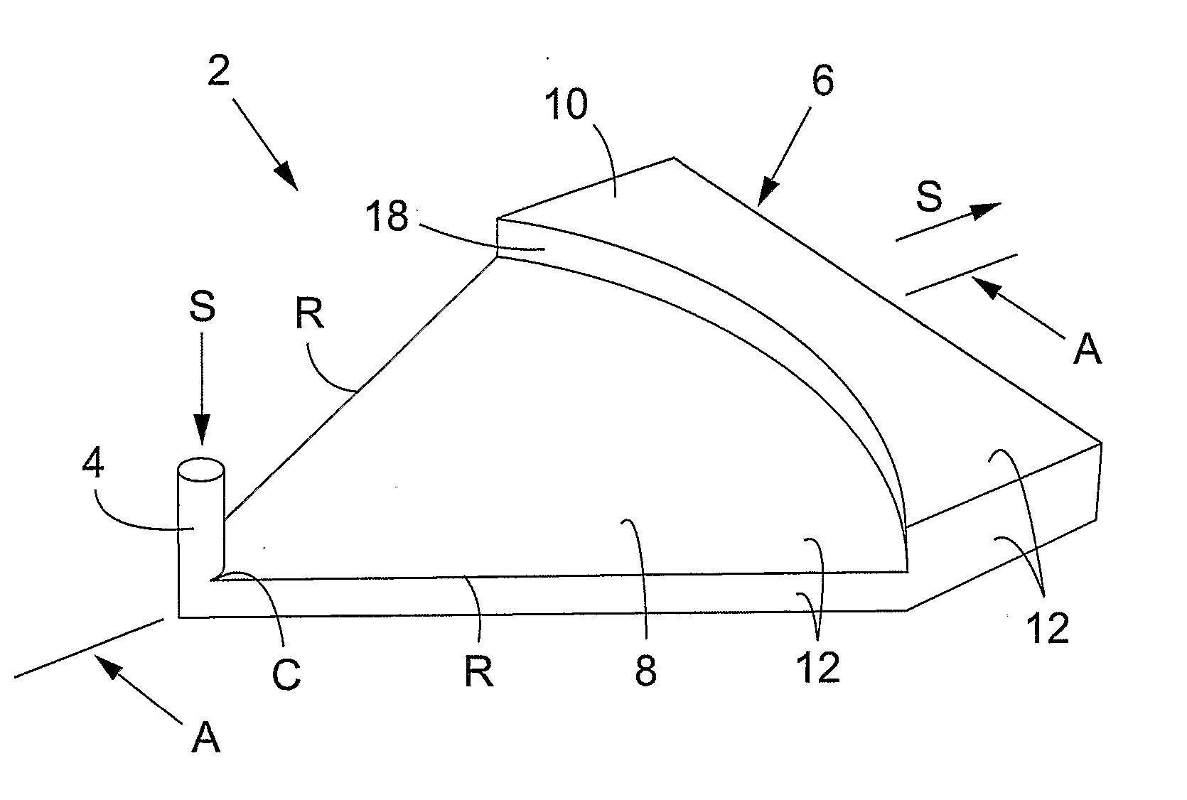
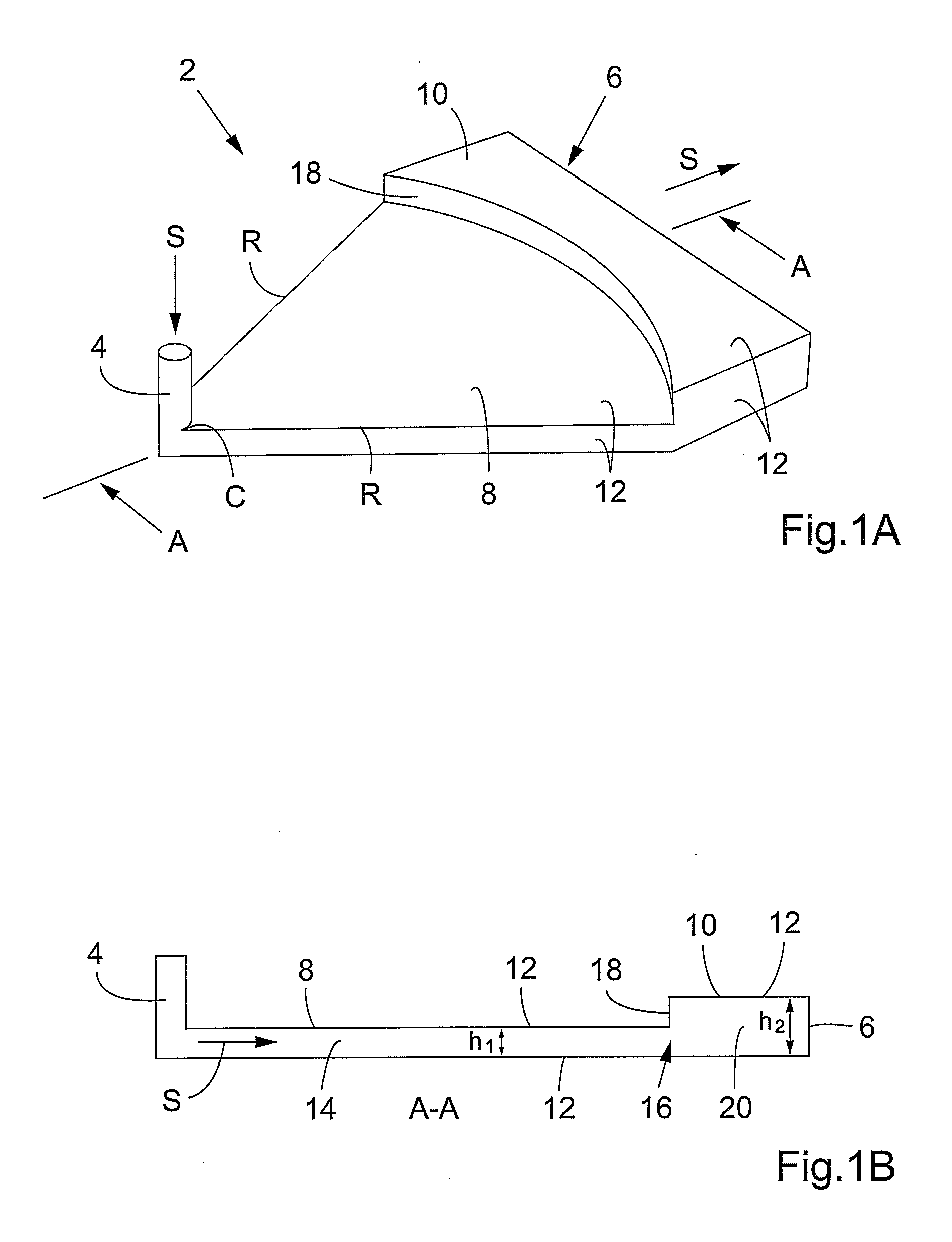
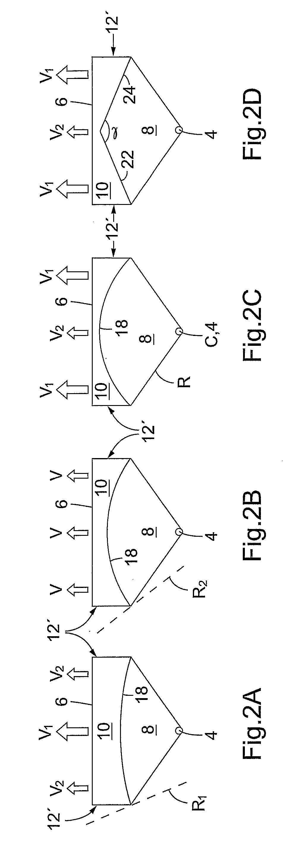
[0036] Turning to the figures, FIGS. 1A and 1B show a distributor according to an embodiment of the present invention for even, transverse distribution and propagation of a flowing medium. The distributor comprises a distribution housing 2 with a conduit 4 for supply of the medium and a wide outlet opening 6. The distribution housing is shaped with a distribution chamber 8 and an outlet chamber 10, which chambers are formed by limiting surfaces 12, whose inner faces are denoted as frictional surfaces. The supply conduit 4 in FIG. 1 is arranged at an angle to the distribution chamber 8, but may also be arranged in parallel to the direction of the flow S. The distribution chamber 8 has a distribution gap 14 that extends from the connection of the conduit in a diverging, conical propagation to a passage 16 having an edge 18, extending substantially transverse to the direction of the flow, with a radius of curvature R, which edge 18 e.g. has the shape of an arc, at which passage 16 the ...


PUM


Abstract

Methods for achieving even transverse distribution and propagation of a flowing medium are disclosed in which the flowing medium is supplied through a conduit and is deflected during diverging propagation in at least one distribution gap The method includes deflecting the flowing medium during diverging propagation along the distribution gap in which the medium is conveyed through a passage to an outlet gap having a larger depth than the depth of the distribution gap. The medium is conveyed over an edge of the passage extending transverse to the direction of the flow, and the edge is designed to obtain a propagation along the flowing path of the diverging medium that provides a substantially even and parallel flow of the medium along the outlet gap. Apparatus for achieving this method is also disclosed.

Description

FIELD OF THE INVENTION [0001] The present invention relates to a method and apparatus for achieving even transverse distribution and propagation of a flowing medium. BACKGROUND OF THE INVENTION [0002] In the cellulose and paper industries, for example, it is necessary to be able to form webs of fiber suspensions in an even and wide distributed flow in the transverse and longitudinal directions on a base, such as a roll, drum or the like. An uneven formation may thus result in an impaired pulp quality, for example due to fiber damages at subsequent press nips in thicker formed sections, canalization of the washing liquid, and poor efficiency during displacement washing. [0003] Distribution of the flow of the flowing medium is controlled substantially by frictional losses (i.e. pressure drop) when the medium flows through a distributor. In order to ensure an even distribution, propagation and discharge of the medium in the transverse direction along a long and narrow gap, e.g. in a re...

Claims


Application Information

Patent Timeline
Patent Type & Authority Applications(United States)
IPC IPC(8): D21F1/00D21F1/06D21F1/02F15D1/00
CPCD21F1/02F15D1/001D21F1/06
Inventor LUNDBERG, JORGENMELANDER, OLOF
Owner VALMET TECH INC
Learn More