
Electronically controlled mechanical timepiece

a mechanical timepiece and electronic control technology, applied in the field of electronic control mechanical timepieces, to achieve the effect of reducing the influence of air viscosity resistance and prolonging the operation period of the timepi

Inactive Publication Date: 2002-04-16
SEIKO EPSON CORP
View PDF13 Cites 0 Cited by
  • Summary
  • Abstract
  • Description
  • Claims
  • Application Information

AI Technical Summary

Benefits of technology

An object of the present invention is to provide an electronically controlled mechanical timepiece in which the period of operation thereof can be extended by reducing the influence of air viscosity resistance.
The surface of the rotor inertia disk or the rotor member, which serves as the largest-diameter member of the present invention, facing the counter component, such as the main plate, need not be flat, and may have an opening. In such a case, since air at the opening on the side of the rotor rotates together with the rotor, even if the opening is formed in the rotor, a great advantage of reducing air viscosity cannot be obtained. However, since excess weight of the rotor is reduced by forming the opening, frictional loss at the bearing can be limited. In particular, when the opening is formed at the center of the rotor, the inertia of the rotor can be increased while limiting the weight, and this is advantageous. In this case, the advantage is more pronounced when the area of the opening is equal to or more than 1 / 2, more preferably 2 / 3, of the area of the rotor inertia disk or the rotor member.

Problems solved by technology

In such a power generator, however, when the gap between the stators, and the main plate or the coil is too small, the above problems are also caused by air viscosity resistance between the components.

Method used


Image

  • Electronically controlled mechanical timepiece
  • Electronically controlled mechanical timepiece
  • Electronically controlled mechanical timepiece

Examples


first embodiment

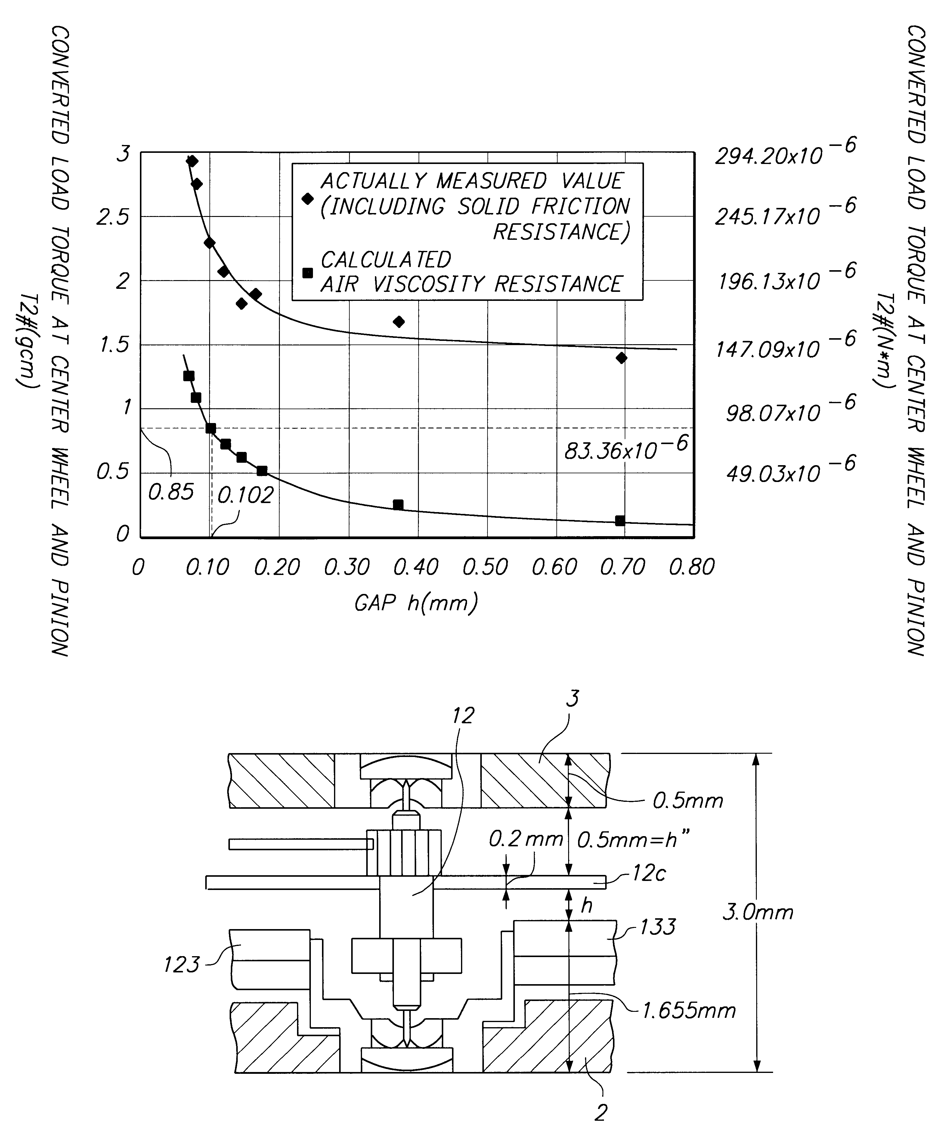
As a first example of the present invention, based on the first embodiment, the load torque T.sub.2# due to air viscosity resistance when the gap h changed, as shown in the following Table 1, was examined by calculation according to the above formula (3) and actual measurement. Table 1 and FIG. 14 show the relationship between the gap h and the load torque T.sub.2#. The load torque T.sub.2# is obtained by converting the load torque T.sub.rz at the rotor 12 into the load torque produced in the center wheel and pinion 7. The formula (6) is a conversion formula. Herein, n represents the speed increasing ratio from the rotor 12 to the center wheel and pinion 7, which is 36,000 in this example, x represents the transmission efficiency per gear from the rotor 12 to the center wheel and pinion 7, which is 0.9 in this example, and y represents the number of engagements from the rotor 12 to the center wheel and pinion 7, which is 5 in this example. In table 1, a lower table shows values obta...

second example

A second example will now be described below. In this example, the relationship among the gap h set according to the formulas (5) and (6) in the first embodiment, the period of operation of the timepiece, and the thickness of the movement was examined.

The conditions in this example are as follows:

air viscosity .mu.: 1.853 Pa.multidot.s (a value obtained by converting 0.189.times.10.sup.-8 gfs / mm.sup.2 into the International System of Units)

rotational frequency f: 8 Hz

distance r.sub.1 : 1.5 mm

distance r.sub.1 : 3.0 mm

mainspring: storable energy.fwdarw.1.106 .mu.J maximum output torque.fwdarw.6.77 N.multidot.m (a value obtained by converting 69 gcm (the maximum output torque T.sub.rzmax to be transmitted to the rotor is 1.4 mgmm (a converted value at the center wheel and pinion is 8.5 gcm) into the International System of Units) effective number of turns.fwdarw.5.72 turns output torque after the effective number of turns are unwound.fwdarw.2.94 N.multidot.m (a value obtained by conver...


PUM


Abstract

A gap h between a rotor inertia disk 12c and stators 123 and 133 is set so that the load torque between the components due to air viscosity resistance is equal to or less than 1 / 10 of the maximum output torque at a rotor. Since the load torque is thereby sufficiently reduced, it is possible to limit energy loss of a mainspring, and to extend the period of operation of a timepiece.

Description

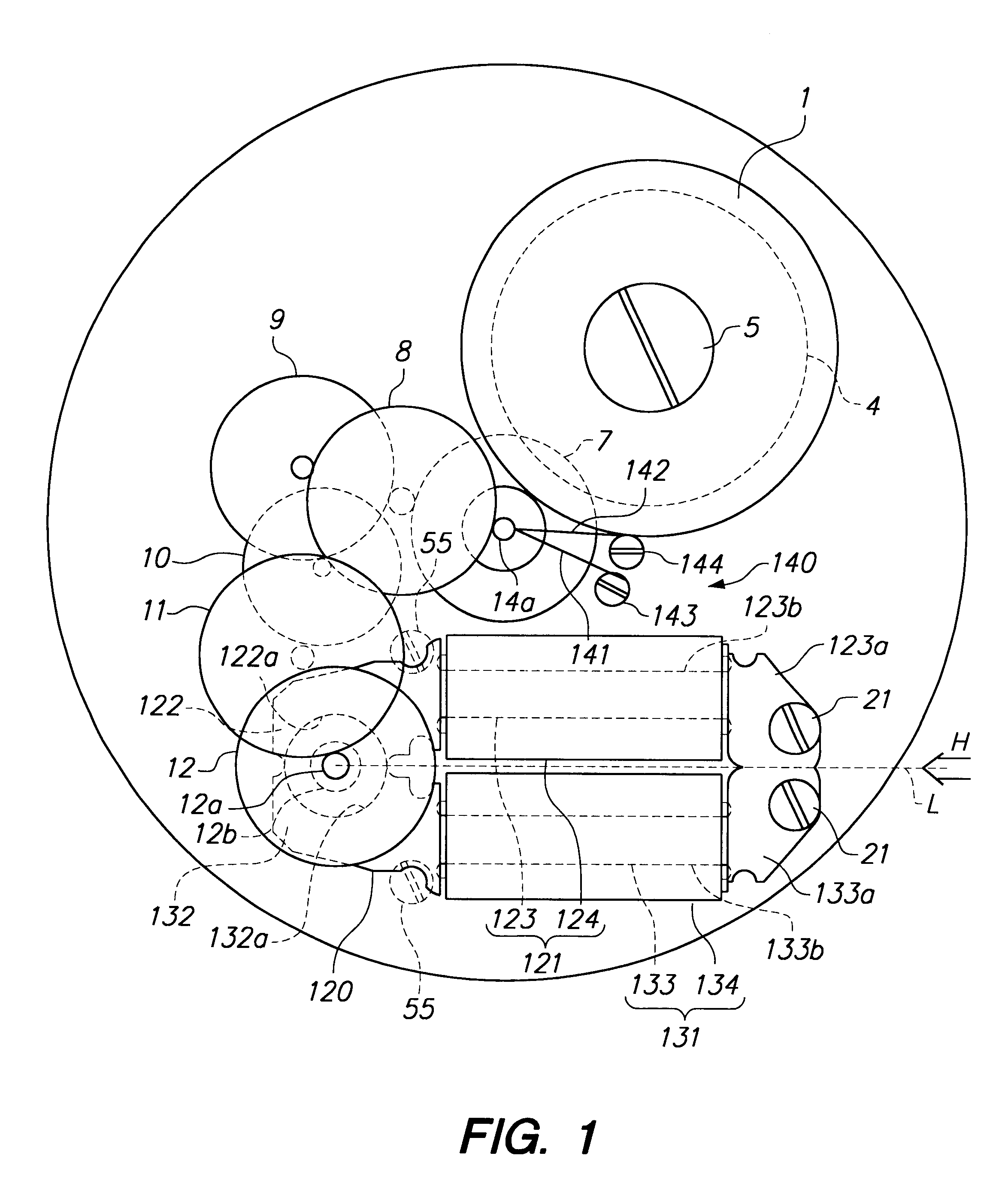
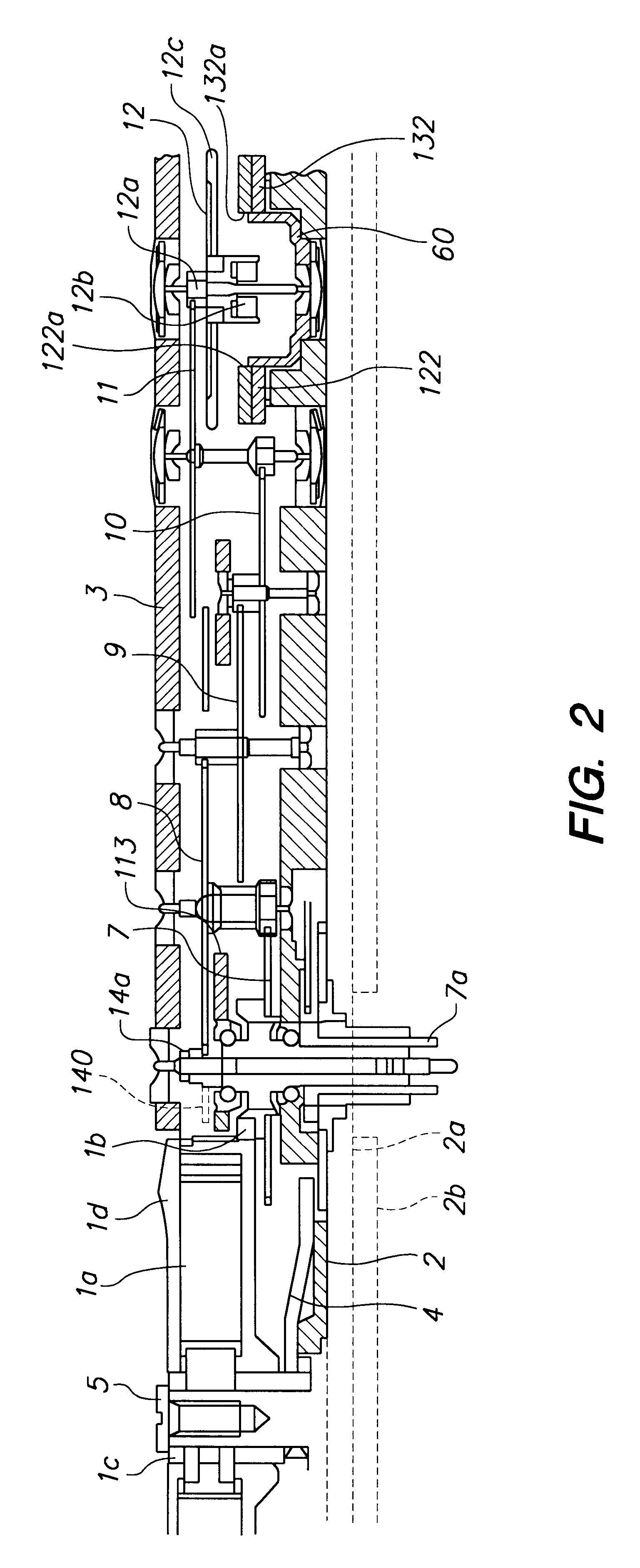
1. Field of the InventionThe present invention relates to an electronically controlled mechanical timepiece which is operated by a mechanical energy storing means, such as a mainspring, serving as a drive source, converts a part of mechanical energy into electrical energy by a power generator, and operates a rotation control means by the electrical power so as to control the rotational cycle. More particularly, the present invention relates to an improvement in the peripheral structure of a power generator for converting mechanical energy into electrical energy.2. Description of the Related ArtJapanese Unexamined Patent Application Publication No. 8-5758 discloses an electronically controlled mechanical timepiece in which mechanical energy generated when a mainspring unwinds is converted into electrical energy by a power generator, the value of current passing through a coil of the power generator, or the like, is controlled by operating a rotation control means by the electrical en...

Claims


Application Information

Patent Timeline
Patent Type & Authority Patents(United States)
IPC IPC(8): G04C10/00G04C3/00G04C13/11G04C13/00
CPCG04C3/008G04C13/11G04C10/00
Inventor MOTEKI, MASATOSHITAKAHASHI, OSAMU
Owner SEIKO EPSON CORP
Learn More