
Clutch control device for four-wheel drive vehicle

a technology of clutch control device and four-wheel drive vehicle, which is applied in the direction of mechanical actuated clutches, interlocking clutches, transportation and packaging, etc., can solve the problems of increased friction of achieve the effect of reducing friction in the drive transmission system, and suppressing friction loss

Active Publication Date: 2017-09-12
NISSAN MOTOR CO LTD
View PDF10 Cites 2 Cited by
  • Summary
  • Abstract
  • Description
  • Claims
  • Application Information

AI Technical Summary

Benefits of technology

The present invention is aimed at providing a clutch control device for a four-wheel drive vehicle that can achieve a balance between securing performance during re-acceleration and reducing friction in the drive transmission system during braking when the foot is lifted off the accelerator in a low-speed region. The clutch control device is capable of automatically switching between the connected, four-wheel drive mode and disconnected, two-wheel drive mode based on the vehicle's speed and the operation of the brakes. This helps to maintain high drive performance while also reducing friction during braking, ultimately improving the vehicle's overall performance.

Problems solved by technology

However, in a conventional device, it is not specified in what type of vehicle state the two-wheel drive mode and the four-wheel drive mode are selected.
Therefore, there is the problem that the friction of the drive transmission system is increased.

Method used


Image

  • Clutch control device for four-wheel drive vehicle
  • Clutch control device for four-wheel drive vehicle
  • Clutch control device for four-wheel drive vehicle

Examples


first embodiment

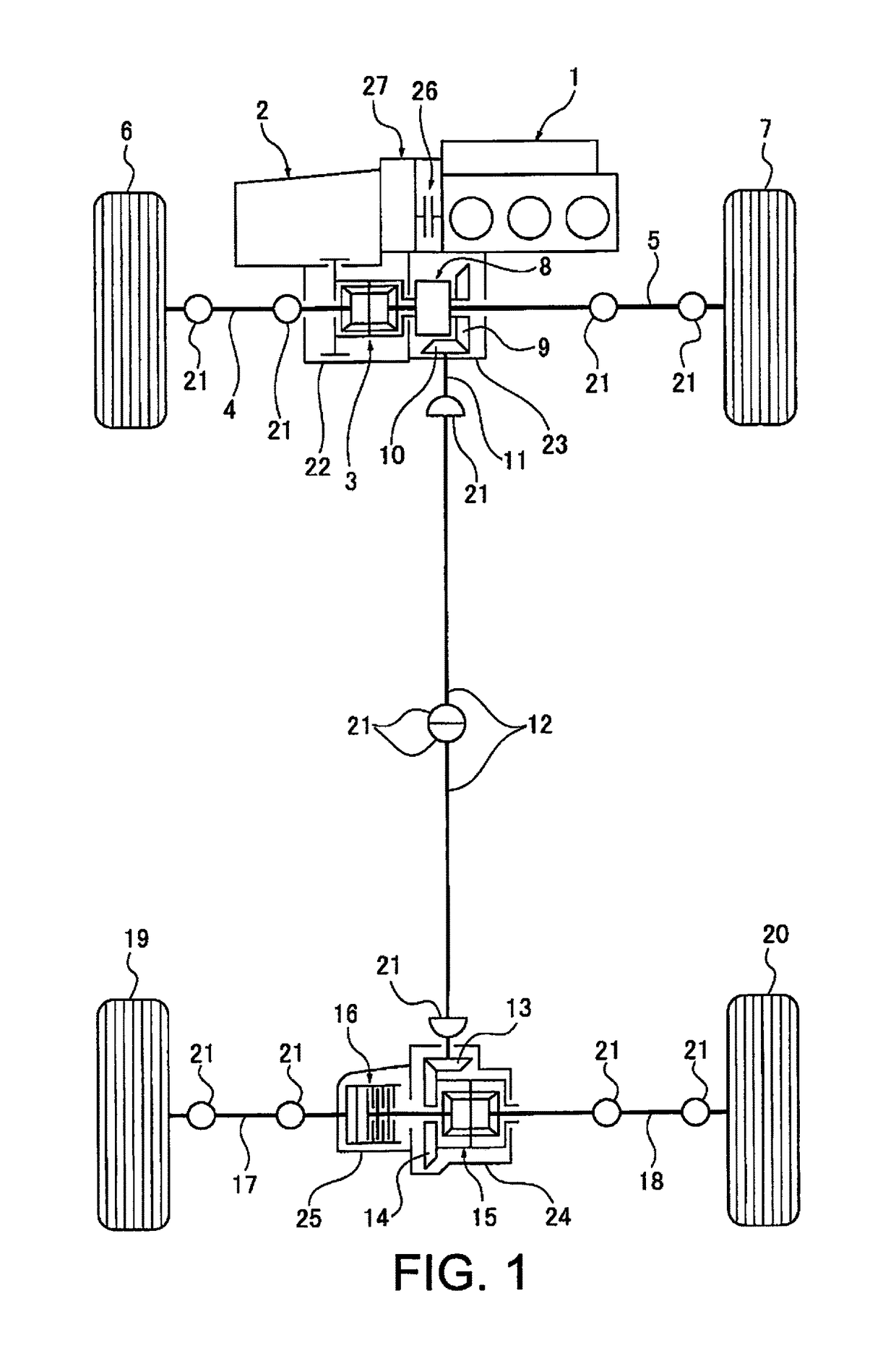
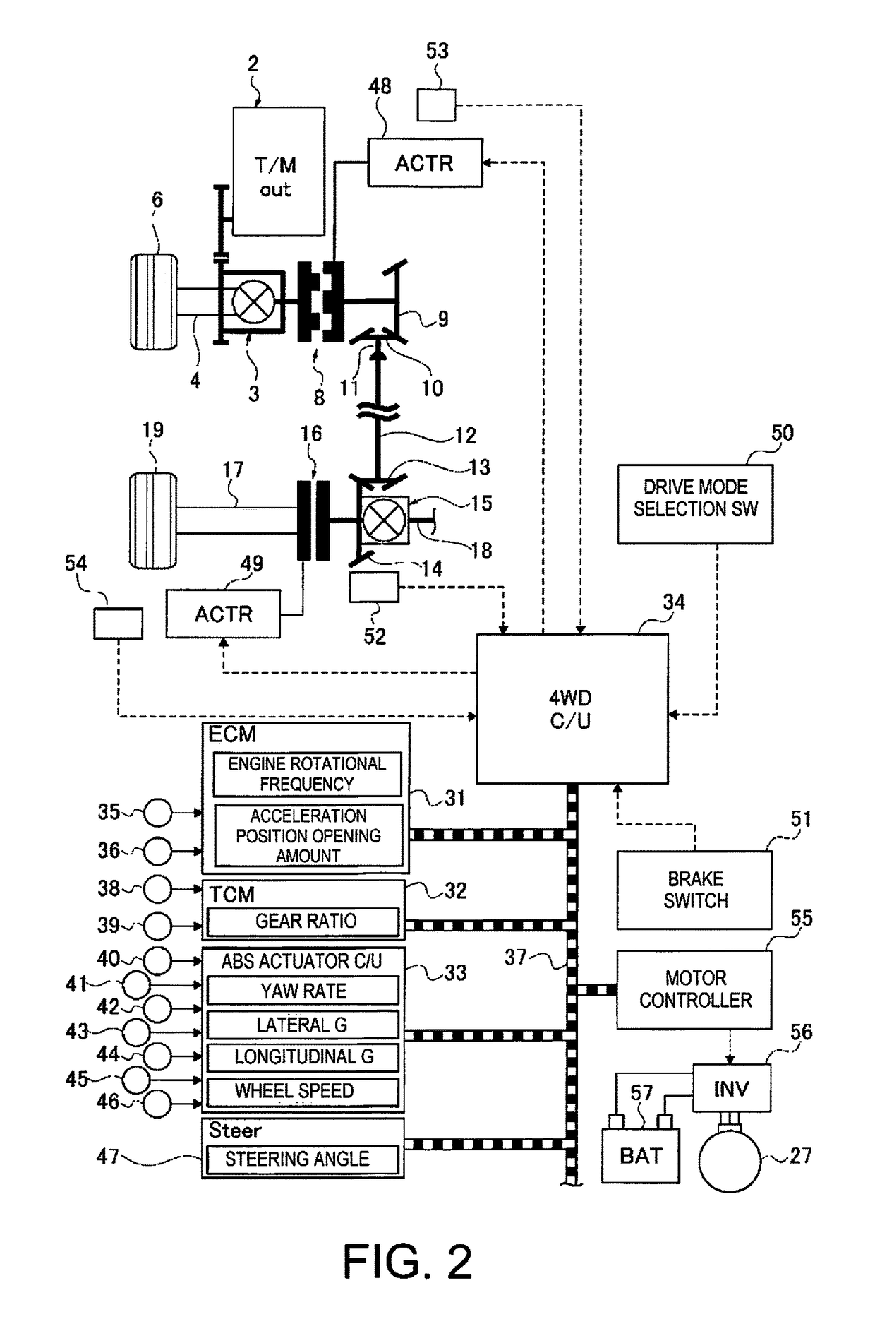
[0018]Referring initially to FIG. 1, a front wheel drive based four-wheel drive vehicle (one example of a four-wheel drive vehicle) is schematically illustrated with a clutch control device in accordance with a first embodiment. The overall configuration of the clutch control device for a drive system configuration of four-wheel drive vehicle will be described first.

Drive System Configuration of the Four-Wheel Drive Hybrid Vehicle

[0019]FIG. 1 illustrates the configuration of the drive system of a four-wheel drive hybrid vehicle to which is applied the clutch control device. The drive system configuration of the four-wheel drive hybrid vehicle will be described below based on FIG. 1.

[0020]The front wheel drive system of a four-wheel drive hybrid vehicle is provided with a transverse engine 1 (drive source), an engine clutch 26, a motor / generator 27 (drive source), and a transmission 2, as illustrated in FIG. 1. A front differential 3, a left front wheel drive shaft 4, a right front w...

second embodiment

[0082]The second embodiment is an example in which the clutch control device is applied to a rear wheel drive based four-wheel drive vehicle, and the positional relationship of the dog clutch and the friction clutch that sandwich the differential is reversed from the positional relationship thereof in the first embodiment.

[0083]FIG. 7 illustrates the configuration of the drive system of a rear wheel drive based four-wheel drive vehicle to which is applied the clutch control device. The drive system configuration of the four-wheel drive vehicle will be described below based on FIG. 7.

[0084]The rear wheel drive system of the four-wheel drive vehicle is provided with a transverse engine 61 (drive source), a transmission 62, a rear propeller shaft 63, a rear differential 64, a left rear wheel drive shaft 65, a right rear wheel drive shaft 66, a left rear wheel 67 (main drive wheel), and a right rear wheel 68 (main drive wheel), as illustrated in FIG. 7. That is, the drive force that has...


PUM


Abstract

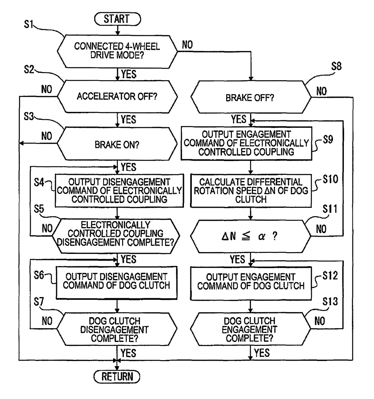
A clutch control device is provided for a four-wheel drive vehicle for transmitting drive force to the rear wheels. The clutch control device includes a dog clutch and a friction clutch, and a controller that controls the engagement and disengagement of the dog clutch and the friction clutch. In this clutch control device, the four-wheel drive hybrid vehicle includes a disconnected, two-wheel drive mode and a connected, four-wheel drive mode. When a driver's foot is lifted off an accelerator in a low-speed region when the connected, four-wheel drive mode is selected, the 4WD control unit maintains the connected, four-wheel drive mode while the brakes are not depressed, and shifts the mode to the disconnected, two-wheel drive mode when the brakes are depressed.

Description

CROSS-REFERENCE TO RELATED APPLICATIONS[0001]This application is a U.S. National stage application of International Application No. PCT / JP2015 / 055253, filed Feb. 24, 2015, which claims priority to JP Patent Application No. 2014-036447 filed on Feb. 27, 2014, the contents of which are hereby incorporated herein by reference.BACKGROUND[0002]Field of the Invention[0003]The present invention generally relates to a clutch control device for a four-wheel drive vehicle in which a system for transmitting drive force to auxiliary drive wheels is provided with a dog clutch and a friction clutch.[0004]Background Information[0005]Conventionally, a front wheel drive based four-wheel drive vehicle in which a system for transmitting drive force to the rear wheels is provided with a dog clutch and a friction clutch is known (refer to, for example, Japanese Laid-Open Patent Application No. 2010-254058). In the four-wheel drive vehicle, when switching from a two-wheel drive mode to a four-wheel drive...

Claims


Application Information

Patent Timeline
Patent Type & Authority Patents(United States)
IPC IPC(8): B60W10/02F16D48/06F16D13/00F16D21/00F16D23/04B60W10/04B60W10/18B60K23/08B60W40/114B60W10/16B60W30/02B60W30/045B60W40/101B60K17/344F16D11/00B60K17/35
CPCB60K23/08B60K17/344B60K23/0808B60W10/02B60W10/04B60W10/16B60W30/02B60W30/045B60W40/101B60W40/114F16D11/00F16D13/00F16D21/00F16D23/04F16D48/06B60K17/3515B60K2023/085B60K6/48B60K2006/4825B60K6/52B60K6/387B60W10/119B60W2520/10B60W2540/12B60W2540/103B60W2540/10B60W10/08B60W30/18127B60W30/18072B60W10/12Y02T10/62B60W2510/1015B60W2510/0638B60W2540/18B60W2510/104B60W2520/105B60W2520/28B60W2510/0604
Inventor OGAWA, KATSUYOSHIMORI, ATSUHIROMITSUISHI, SHUNICHIMORITA, MAKOTOTAKAISHI, TETSU
Owner NISSAN MOTOR CO LTD
Learn More