
Collision obstacle discrimination device

a technology of obstacle discrimination and obstacle, which is applied in the direction of bumpers, instruments, force/torque/work measurement apparatus, etc., can solve the problems of complicated construction, difficult to determine that the obstacles colliding with different parts of the vehicle are of the same kind, and can cause various adverse effects, etc., to achieve the effect of being easily adjusted

Inactive Publication Date: 2007-07-19
DENSO CORP
View PDF3 Cites 55 Cited by
  • Summary
  • Abstract
  • Description
  • Claims
  • Application Information

AI Technical Summary

Benefits of technology

[0008]In view of the above-described disadvantage, it is an object of the present invention to provide a collision obstacle discrimination device, which substantially sort-discriminates an collision obstacle with respect to different collision occurrence positions of a vehicle and has a simplified construction.
[0010]Because the multiple sensor members which have the different detection sensitivities are fixed to the elongated member in the vehicle width direction, the construction and the mounting of the collision obstacle discrimination device can be simplified. Moreover, because the plurality of sensor members have a substantially same response property with respect to the load applied to the bumper, the subsequent process can become easy.
[0014]Thus, the sensitivity (i.e., amplitude of pressure which can be detected) of the sensor member can be readily adjusted by an alteration of the composition and the like of the pressure sensitive ink.

Problems solved by technology

However, various adverse effects will be caused in the case where the pedestrian protecting device is actuated despite the obstacle is not the pedestrian.
In this case, when a load sensor has the different sensitivities in response to the different collision occurrence portions (at vehicle) in the vehicle width direction, it is difficult to determine that the obstacles colliding with different parts of the vehicle are of the same sort despite the obstacles are of the same sort.
However, as disclosed in WO-2004-033261A, a complicated construction is used to locally change the transference of the impact (due to collision) with respect to the each part of the load sensor.

Method used


Image

  • Collision obstacle discrimination device
  • Collision obstacle discrimination device
  • Collision obstacle discrimination device

Examples


embodiments

First Embodiment

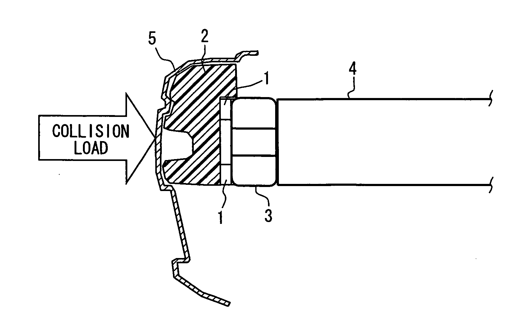
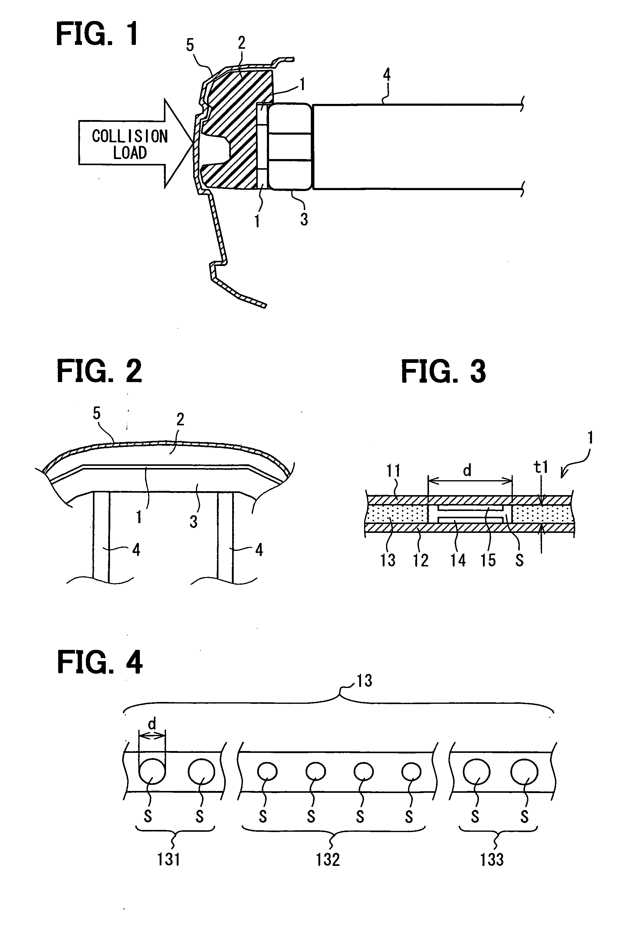
[0025]A collision obstacle discrimination device according to a first embodiment of the present invention will be described with reference to FIGS. 1-8B. The collision obstacle discrimination device can be suitably used for a vehicle, for example. In this case, the collision obstacle discrimination device can be arranged at a front portion of the vehicle, for example, at a front side of an engine cabin of the vehicle. As shown in FIGS. 1 and 2, the collision obstacle discrimination device has at least one load sensor 1 and a calculation unit (not shown).

[0026]A bumper of the vehicle is provided with a bumper absorber 2, which is arranged in a bumper cover 5 and extends in the vehicle width direction to absorb a collision energy (i.e., buffer impact) in the case of a collision of the vehicle. The bumper absorber 2 can be constructed of a foam material, for example.

[0027]In this case, the two load sensors 1, which are positioned in the bumper, are sandwiched between th...

second embodiment

[0061]According to a second embodiment of the present invention, with reference to FIG. 9, the collision obstacle discrimination device can be provided with the load sensor 1 which includes multiple chamber type load sensor members (e.g., three chamber type load sensor members 1a, 1b and 1c).

[0062]In the second embodiment, each of the chamber type load sensor members 1a, 1b and 1c includes a chamber which is closed and provided with gas such as air therein, and a pressure detection unit which can be arranged in the chamber to detect a pressure in the chamber. That is, the elongated member of the load sensor 1 defines therein the chambers which are respectively closed (i.e., independent of each other) and sequentially arrayed in the vehicle width direction. In this case, the spacer 13 is not used.

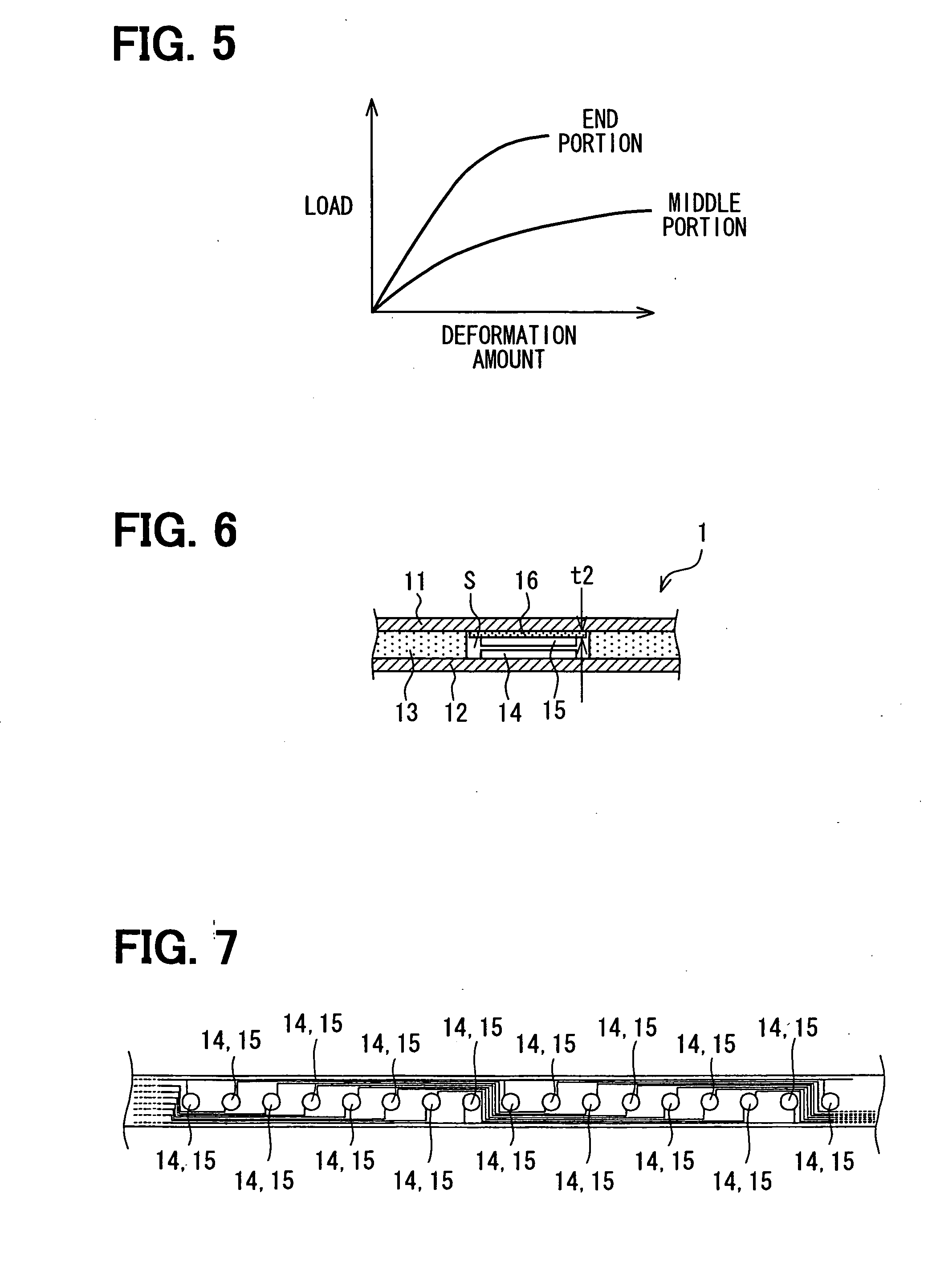
[0063]As described above, the collision load applied to the bumper is more easily transferred to the sensor member which is arranged in the vicinity of the middle portion of the bumper than ...

third embodiment

[0068]According to a third embodiment of the present invention, the load sensor 1 of the collision obstacle discrimination device is constructed of a tube type load sensor (not shown). The tube type load sensor 1 has a tube (elongated member). One end of the tube of the tube type load sensor 1 is blocked, and the inner pressure is detected at the other end thereof. The tube type load sensor 1 is mounted to the bumper, and extends to the substantially whole bumper in the vehicle width direction. In this case, the spacer 13 is not used.

[0069]As described above, the bumper has different deformation (due to collision load, for example) at the different part thereof. According to the third embodiment, the different parts of the tube can be provided with the different stiffness. For example, in the case where the same load is applied, the part (of the tube) which has a small deformation due to the load can be provided with a low stiffness, and the part (of the tube) which has a large defo...


PUM


Abstract

A collision obstacle discrimination device has a load sensor. The load sensor includes an elongated member which is arranged in a bumper of a vehicle and extends substantially in a width direction of the vehicle, and a plurality of sensor members which are fixed in a space defined by the elongated member and arrayed in the vehicle width direction. The sensor member is disposed to detect a physical property which varies in response to a load applied to the bumper due to a collision of the vehicle. Sensitivities of the plurality of sensor members are respectively set in response to vehicle-width-direction positions of the sensor members to be diversified, so that the plurality of sensor members have a substantially same response property with respect to the load applied to the bumper.

Description

CROSS REFERENCE TO RELATED APPLICATION[0001]This application is based on a Japanese Patent Application No. 2006-8858 filed on Jan. 17, 2006, the disclosure of which is incorporated herein by reference.FIELD OF THE INVENTION[0002]The present invention relates to a collision obstacle discrimination device which can be suitably used for a vehicle to sort-discriminate an obstacle colliding with the vehicle.BACKGROUND OF THE INVENTION[0003]Generally, it is desirable to protect a pedestrian from a collision with a vehicle. Therefore, various pedestrian protecting devices are proposed. However, various adverse effects will be caused in the case where the pedestrian protecting device is actuated despite the obstacle is not the pedestrian. Accordingly, it is necessary to determine whether or not the collision obstacle is a pedestrian.[0004]For example, as disclosed in JP-11-310095A, the discrimination of the pedestrian is performed, based on the increase rate of a collision load after the co...

Claims


Application Information

Patent Timeline
IPC IPC(8): B60R19/02B60R19/48B60R21/00G01L5/00
CPCB60R19/483
Inventor TANABE, TAKATOSHI
Owner DENSO CORP
Features
  • Generate Ideas
  • Intellectual Property
  • Life Sciences
  • Materials
  • Tech Scout
  • Unparalleled Data Quality
  • Higher Quality Content
  • 60% Fewer Hallucinations
Learn More