Mounting system for grinding wheels and the like

a technology of mounting system and grinding wheel, which is applied in the direction of grinding machine components, grinding machines, manufacturing tools, etc., can solve the problem of not providing sufficient holding power for high rpm applications

Inactive Publication Date: 2007-07-19
NAO ENTERPRISE
View PDF20 Cites 37 Cited by
  • Summary
  • Abstract
  • Description
  • Claims
  • Application Information

AI Technical Summary

Problems solved by technology

While such systems are satisfactory for low rpm operation, they m

Method used


Image

  • Mounting system for grinding wheels and the like
  • Mounting system for grinding wheels and the like
  • Mounting system for grinding wheels and the like

Examples


Embodiment Construction

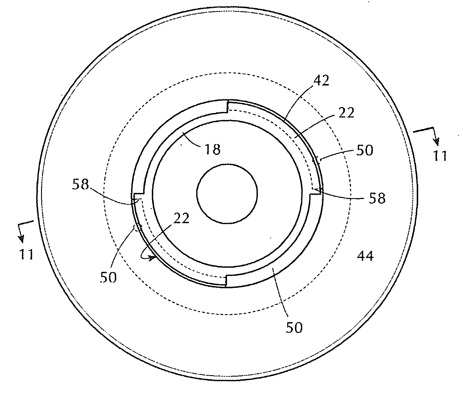
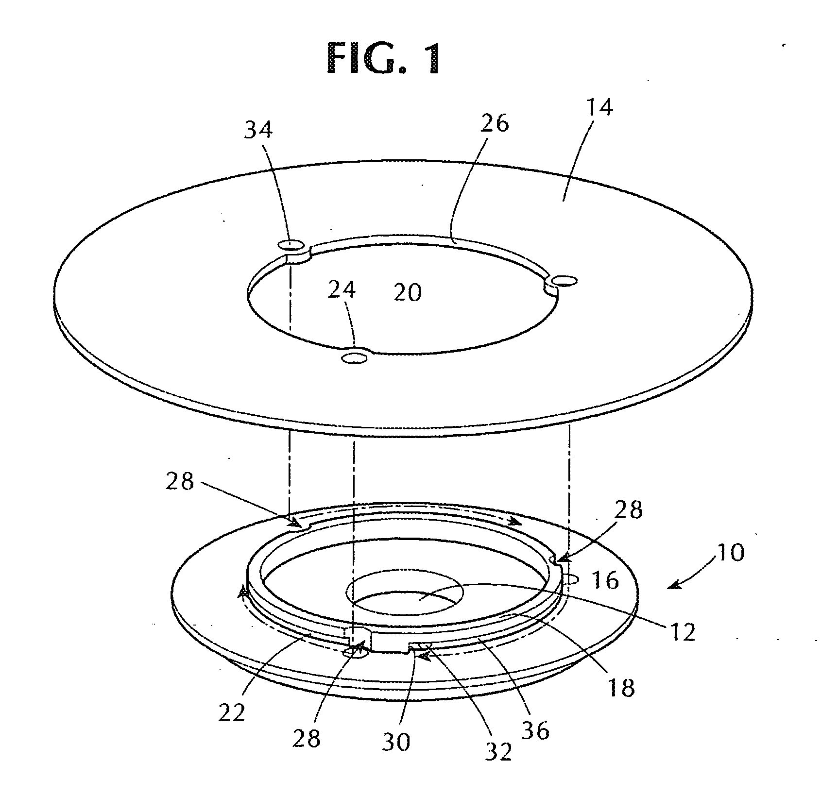
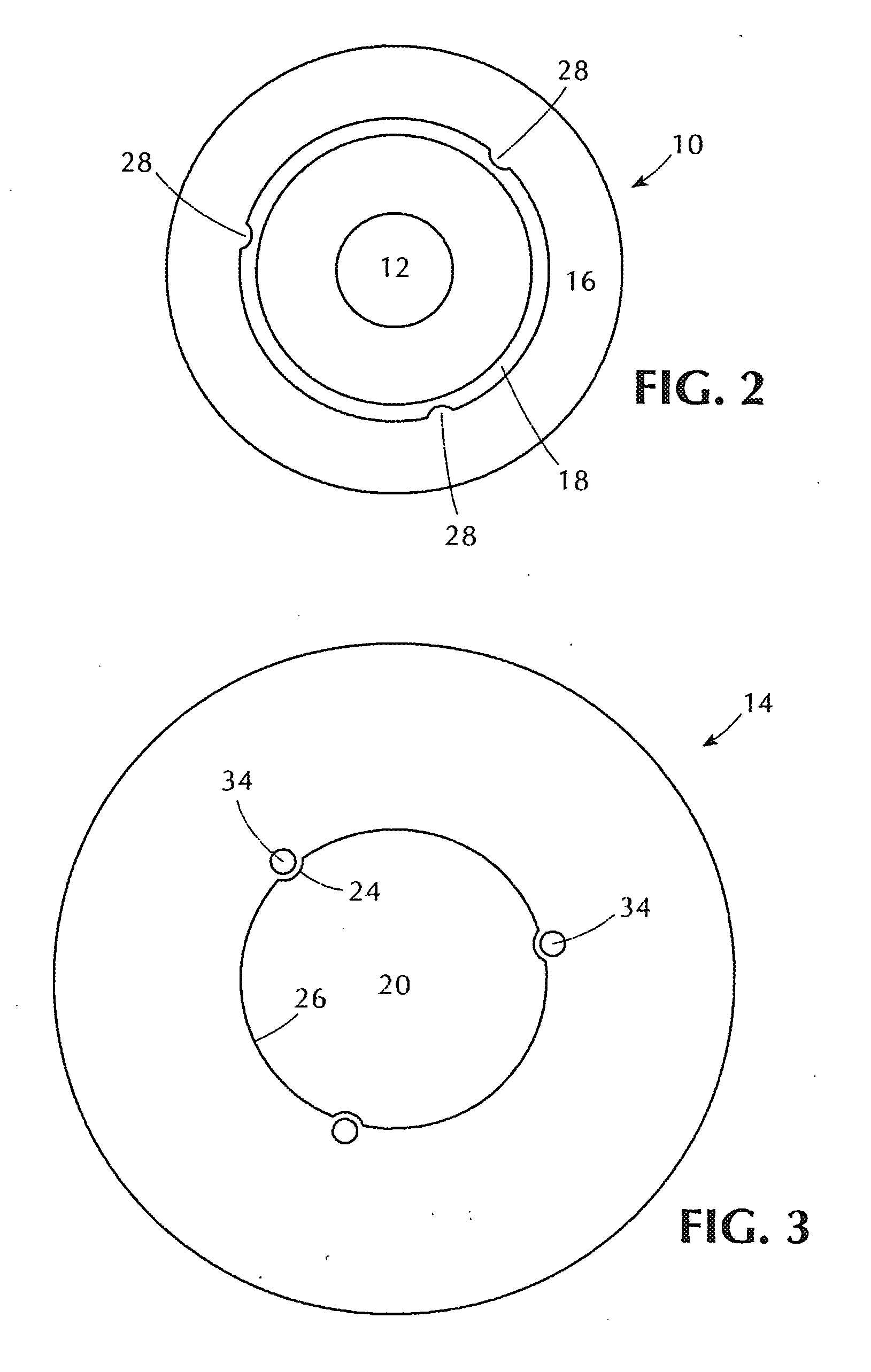
[0021] With initial reference to FIG. 1, the mounting system of the present invention comprises a generally circular hub 10, adapted to be mounted upon an arbor of a motorized tool, and particularly upon the arbor of a hand-held tool. The hub includes a central mounting bore 12 to accept the tool arbor or shaft, and may include recesses on its bottom face (not shown) to engage complementary lugs on an arbor flange. The hub is retained on the arbor shaft by means as known in the art, as by a flange and lock nuts. Circular tool element 14 is removably mounted to the hub. As recognized in the art, tool element 14 may be a retaining member to which a working element, such as a sandpaper disk or grinding member is affixed, or may itself comprise a cut-off wheel assembly or circular saw blade unit. The tool element is installed upon the hub by being moved axially with respect to the arbor into contact with hub face 16 and then rotated with respect to the hub into a retained and locked pos...


PUM


Abstract

A mounting system for rotating tools such as grinding wheels in a hand-held power tool, includes a hub mountable to the tool drive shaft and a rotating tool element removably affixable to the hub. The tool has at least one flange that engages a corresponding circumferential groove in a hub wall. Both the hub and tool have complimentary lock elements to frictionally retain the tool in a releasably fixed orientation upon the hub. One of the lock elements is in the form of a depression, while a mating element located on the other ports is a complimentary projection.

Description

[0001] The present invention relates to a mounting system for affixing rotating tools, such as grinding wheels, circular saw blades, and the like to a tool arbor such is found in hand-held power tools. BACKGROUND OF THE INVENTION [0002] Hand-held power tools, such as grinders, sanders, saws, and the like include a motor driven arbor shaft to which is mounted an appropriate tool head, such as a grinding wheel, sanding disk, or circular saw blade. The arbor is typically threaded, allowing a tool hub to be affixed thereon, such as by a mounting nut assembly. The hub may be an integral part of the rotary tool, but often a hub is provided as an intermediate coupling unit between the arbor and the tool element, which is removably mounted to the hub. This latter form of tool head construction is often preferred, as it allows the work-engaging tool element, such as a grinding wheel, to be removed from the hub when worn without disengaging the hub itself from the arbor shaft. Further, such a...

Claims


Application Information

Patent Timeline
IPC IPC(8): B24B27/08
CPCB24D5/16B24B45/006
Inventor MOMOSAKI, MITSUKAZU
Owner NAO ENTERPRISE
Why Eureka
Try Eureka