Wound drain removal device

Inactive Publication Date: 2007-07-19
BACTERIN INT
View PDF1 Cites 3 Cited by
  • Summary
  • Abstract
  • Description
  • Claims
  • Application Information

AI Technical Summary

Problems solved by technology

Breakage or fragmentation of wound drains during removal from patients is a major complication of the use of wound drains for post-operative wound management.
In either situation, a healthcare provider following the conventional method of pulling until the wound drain is removed from the patient will cause wound drain breakage, resulting in fragments of the wound drain being left inside the patient.
These retained fragments require a second surgical exploration and necessitate additional expense and risk to the patient.
These increased risks include operative morbidity and secondary wound infection.

Method used


Image

  • Wound drain removal device
  • Wound drain removal device
  • Wound drain removal device

Examples


Embodiment Construction

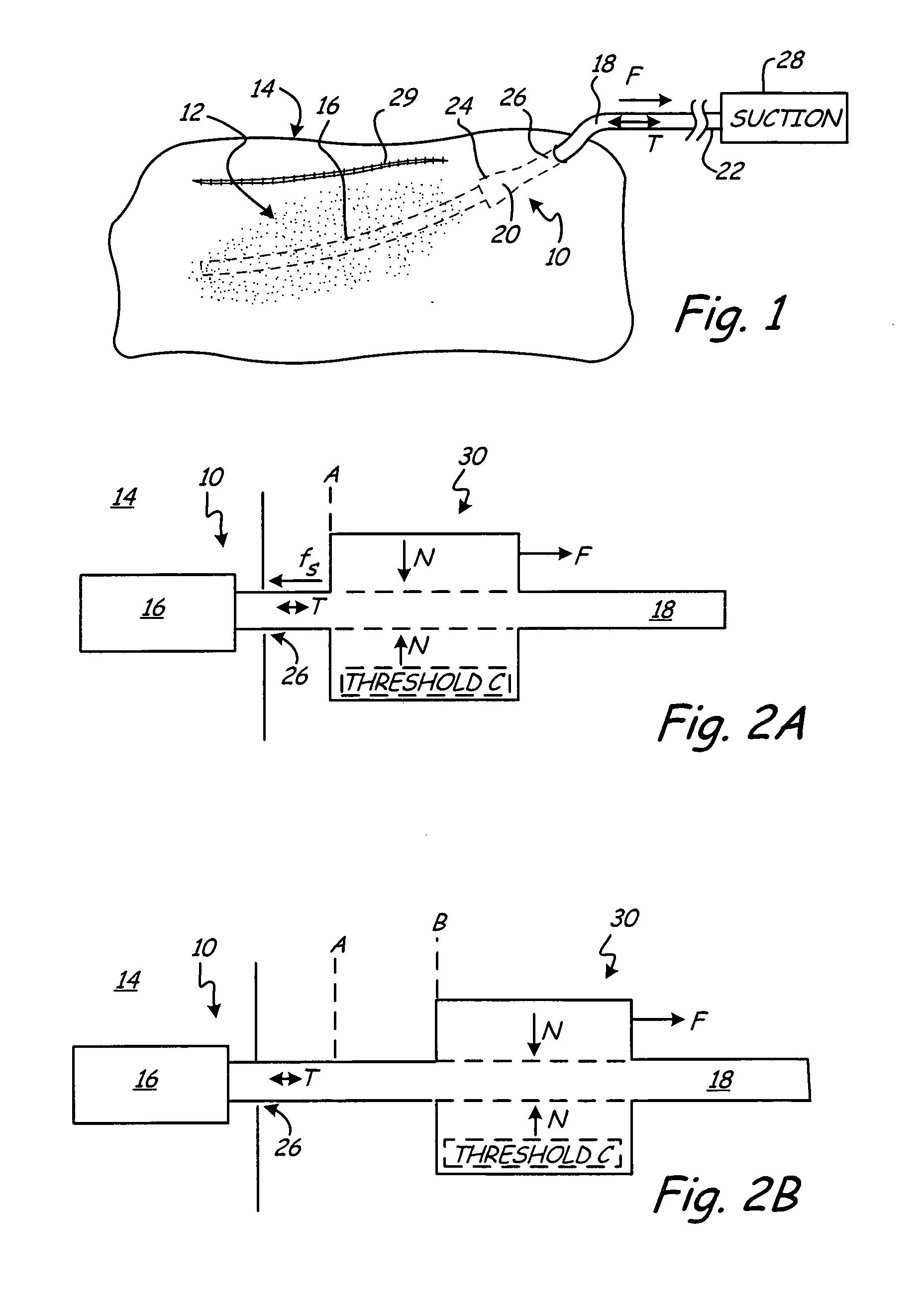
[0027]FIG. 1 is a schematic representation of wound drain 10 implanted within wound 12 of patient 14. Wound drain 10 includes drain 16 and outflow tube 18 having distal end 20 and proximal end 22. Distal end 20 of outflow tube 18 connects to wound drain 10 via connection 24.

[0028] To drain fluid from wound 12, drain 16 is located within, or adjacent, to wound 12 and is in fluid communication with outflow tube 18. Outflow tube 18 exits patient 14 via aperture 26 formed in tissue adjacent to wound 12. Proximal end 22 connects to an external suction source 28 to draw fluid from wound 12 into drain 16 and through outflow tube 18 to a reservoir associated with external suction source 28.

[0029] Methods for implanting wound drain 10 within patient 14 are well known in the art. For example, in one such method, drain 16 is positioned within, or adjacent to, wound 12. A trocar (not shown in FIG. 1) attached to proximal end 22 of outflow tube 18 is passed through tissue adjacent to wound 12 ...


PUM


Abstract

A wound drain removal device allows an implanted wound drain to be removed from a patient in a manner that limits the amount of tension that develops within the wound drain. The wound drain removal device includes a gripping surface and a handgrip for applying a pulling force to an outflow tube of the wound drain. The gripping surface is configured to slip relative to an outer surface of the outflow tube when a removal force associated with removal of the wound drain exceeds a predetermined threshold force.

Description

BACKGROUND OF THE INVENTION [0001] The present invention relates generally to wound drains. More specifically, the present invention relates to a device and method for limiting an amount of tension placed on an implanted wound drain during removal from a patient. [0002] Wound drains are used to drain fluid from wounds and generally include a drain and an outflow tube. Wound drains are placed in a wound area during surgical wound closure to provide an avenue for tissue fluids to exit the wound. The drain resides under the skin within, or near, the wound while the outflow tubing is external to the skin and connects to a suction reservoir. Both the drain and outflow tubing are typically made of an elastic polymer such as silicone. [0003] The conventional method for removing a wound drain from a patient is to pull on the outflow tubing until the wound drain comes out of the patient. Breakage or fragmentation of wound drains during removal from patients is a major complication of the use...

Claims


Application Information

Patent Timeline
IPC IPC(8): A61B17/00
CPCA61M27/00
Inventor JOHNSON, MICHAEL THOMAS VINCENT
Owner BACTERIN INT
Why Eureka
Try Eureka