Two-stage turbocharger system with integrated exhaust manifold and bypass assembly

Active Publication Date: 2007-07-26
GARRETT TRANSPORATION I INC
View PDF4 Cites 86 Cited by
  • Summary
  • Abstract
  • Description
  • Claims
  • Application Information

AI Technical Summary

Benefits of technology

[0005] The present invention addresses the above needs and achieves other advantages by providing a two-stage turbocharger system that includes an exhaust manifold formed separately from the high-pressure and low-pressure turbine housings. The exhaust manifold defines a bypass passage, and a bypass valve is disposed in the bypass passage for opening and closing the passage. The exhaust manifold also defines an inter-turbine passage. The turbine housings of the

Problems solved by technology

Such arrangements become mechanically complex and entail multiple connections between components that are subject to leakage

Method used


Image

  • Two-stage turbocharger system with integrated exhaust manifold and bypass assembly
  • Two-stage turbocharger system with integrated exhaust manifold and bypass assembly
  • Two-stage turbocharger system with integrated exhaust manifold and bypass assembly

Examples


Embodiment Construction

[0014] The present inventions now will be described more fully hereinafter with reference to the accompanying drawings in which some but not all embodiments of the inventions are shown. Indeed, these inventions may be embodied in many different forms and should not be construed as limited to the embodiments set forth herein; rather, these embodiments are provided so that this disclosure will satisfy applicable legal requirements. Like numbers refer to like elements throughout.

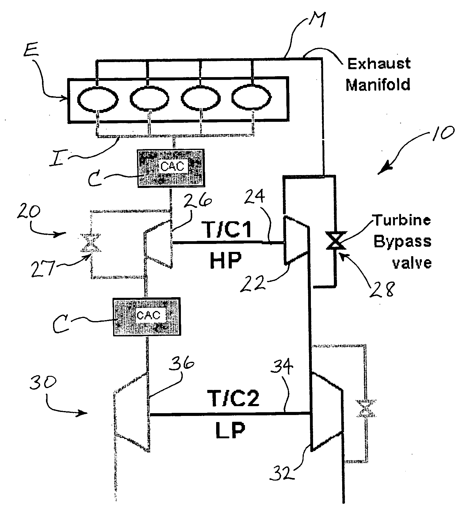
[0015]FIG. 1 is a schematic illustration of an internal combustion engine E to which a two-stage turbocharger system 10 is coupled for boosting performance of the engine. The turbocharger system 10 comprises a high-pressure turbocharger 20 and a low-pressure turbocharger 30. The high-pressure turbocharger comprises a high-pressure turbine 22 connected by a shaft 24 to a high-pressure compressor 26. The low-pressure turbocharger 30 comprises a low-pressure turbine 32 connected by a shaft 34 to a low-pressure co...


PUM


Abstract

A two-stage turbocharger system includes an exhaust manifold formed separately from the high-pressure and low-pressure turbine housings. The exhaust manifold defines a bypass passage, and a bypass valve is disposed in the bypass passage for opening and closing the passage. The exhaust manifold also defines an inter-turbine passage. The turbine housings of the high-pressure and low-pressure turbochargers are releasably connected to the exhaust manifold such that exhaust gas received into the exhaust manifold bypasses the high-pressure turbine and flows through the bypass passage to the low-pressure turbine when the bypass valve is in the open position, and the exhaust gas flows through the high-pressure turbine and then through the inter-turbine passage to the low-pressure turbine when the bypass valve is in the closed position.

Description

BACKGROUND OF THE INVENTION [0001] The present invention relates to turbochargers, and more particularly relates to two-stage turbocharger systems. [0002] The performance of internal combustion engines can be enhanced with the use of a turbocharger for increasing the pressure of the air supplied to the engine intake. In a simple turbocharger system, a single turbocharger is coupled with the engine. The turbocharger includes a turbine driven by exhaust gas from the engine exhaust manifold, and a compressor driven by the turbine for compressing air before it is delivered to the engine intake. The increased pressure of the intake air enables the engine to produce a greater amount of power. [0003] In many engine systems, a single turbocharger is adequate. In other cases, however, it is desirable to provide maximum boost pressures that cannot readily be achieved with a single turbocharger. Accordingly, it is known to employ two turbochargers arranged in series. A low-pressure turbocharge...

Claims


Application Information

Patent Timeline
IPC IPC(8): F02B33/44F01N13/10F01N13/18
CPCF01N13/10F02B37/007F02B37/013F02B37/004F02B37/183Y02T10/144F02B37/18Y02T10/12
Inventor NICOLLE, FREDERIC F.WILKINS, CHRISTOPHERCAPELLI, MAGALI M.
Owner GARRETT TRANSPORATION I INC
Why Eureka
Try Eureka