Gantry positioning system

a positioning system and gantry technology, applied in transportation and packaging, hoisting equipment, manufacturing tools, etc., can solve the problems of low precision, inconvenient operation, and inherent drawbacks of ball screws

Active Publication Date: 2007-07-26
ASMPT SINGAPORE PTE LTD
View PDF25 Cites 19 Cited by
  • Summary
  • Abstract
  • Description
  • Claims
  • Application Information

AI Technical Summary

Benefits of technology

[0009] It is thus an object of the invention to seek to provide a gantry positioning system that reduces some of the aforesaid disadvantages of prior art gantry systems to achieve simplicity and placement accuracy.

Problems solved by technology

However, ball screws have inherent drawbacks such as relatively slow speed and lower precision.
A disadvantage of such a design is that it does not cater to thermal expansion during operation and possible asynchronous operation of the motors driving the beam.
Positioning accuracy will be affected and the slide rails will also face excessive loads and greater wear.
This compensates for thermal expansion and asynchronous operation, but on the other hand, it introduces various design complexities.
Unfortunately, an excess of rotary degrees of freedom leads to the gantry system having limited stiffness to counter roll and pitch movements, which ought to be high in order to achieve the requisite accuracy and dynamic performance.

Method used


Image

  • Gantry positioning system
  • Gantry positioning system
  • Gantry positioning system

Examples


Embodiment Construction

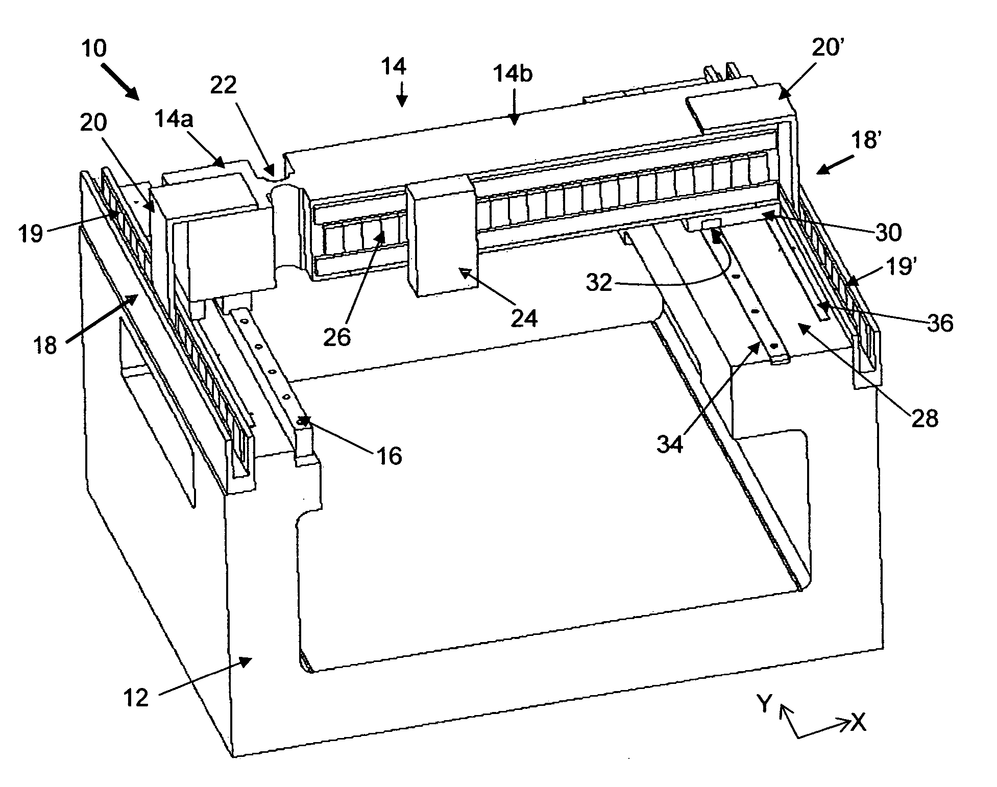
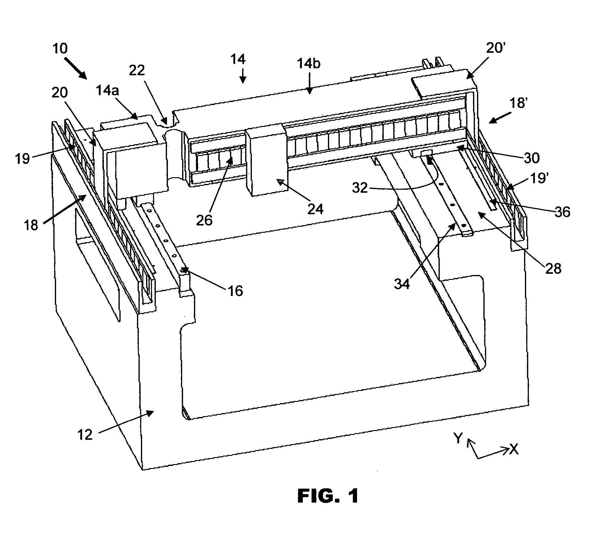
[0019]FIG. 1 is an isometric view of a gantry system 10 according to the preferred embodiment of the invention. The gantry system 10 generally comprises a base support 12 which includes vertical sidewalls, a gantry beam 14 having separate sections 14a, 14b and supported at its respective ends by each vertical sidewall, a linear guide such as a guide rail 16 for guiding movement of one section 14a of the gantry beam 14 along one vertical sidewall, and a bearing such as an air bearing for supporting a second section 14b of the gantry beam 14 along the other vertical sidewall.

[0020] There is a pair of motors, which may be in the form of linear motors 18, 18′ each driving a respective end of the first section 14a and the second section 14b substantially synchronously in parallel directions to position the gantry beam 14 along a linear axis (ie. the Y axis in FIG. 1). Each linear motor 18, 18′ comprises a magnet assembly 19, 19′ including rows of magnets cooperating with a coil bracket ...


PUM


Abstract

A gantry system is provided that comprises a gantry beam having a first section and a second section and first and second motors cooperating to drive the respective first and second sections in parallel directions to position the gantry beam along a linear axis. A flexure is connected between the first and second sections about which the second section is deflectable relative to the first section, which is advantageous to reduce any stresses that may be caused in the gantry system when driving the gantry beam.

Description

FIELD OF THE INVENTION [0001] The invention relates to a movable gantry system on which a device is mountable for performing an operation within a work area, and in particular to a system for precisely controlling a position of the movable gantry. BACKGROUND AND PRIOR ART [0002] Gantry systems can be widely used for a range of applications, from assembly and electronic manufacturing, to vision systems and industrial automation. In semiconductor assembly and packaging, positioning systems using gantries are useful where a work space spans a predefined area and it is necessary to position a device accurately at various positions within the area. [0003] References herein to gantry systems are to be understood as including multi-axis positioning systems whereby a device is required to be accurately positioned in a two dimensional plane or a three dimensional space. In a typical two dimensional arrangement, the device is supported by a carriage which is movable back and forth in a first ...

Claims


Application Information

Patent Timeline
Patent Type & Authority Applications(United States)
IPC IPC(8): B66C17/00B66C19/00
CPCB23Q2210/002B23Q1/012
Inventor GAUNEKAR, AJITWIDDOWSON, GARY PETER
Owner ASMPT SINGAPORE PTE LTD
Why Eureka
Try Eureka