Permanent-magnet magnetic actuator of reduced volume

a magnetic actuator and permanent technology, applied in the direction of electromagnets, magnetic bodies, electrical appliances, etc., can solve the problems of difficult modulation, large amount of material used for a given drive force, bulky, etc., and achieve the effect of convenient actuator securemen

Inactive Publication Date: 2007-07-26
AREVA T&D
View PDF24 Cites 29 Cited by
  • Summary
  • Abstract
  • Description
  • Claims
  • Application Information

AI Technical Summary

Benefits of technology

[0028] It is advantageous for the end plate of the yoke to include a groove in its face remote from the magnet in order to make it easier to secure the actuator on a support.

Problems solved by technology

The drawback of actuators that are axially symmetrical, such as the actuator described in patent application EP-A-1 225 609, or even in patent application FR-A-2 504 718 which relates to a self-holding solenoid, is that they are difficult to modulate so as to obtain a range of actuators for providing different drive forces.
The magnets are in the form of circular arcs, and they are therefore not easy to make.
A drawback of the FIG. 1 actuator is that magnetic flux that becomes established in the magnetic circuit, in particular because of the presence of the magnets 6, passes between the armature 7 and the yoke 5 transversely to the axis x-x′.
These parts need to be mounted with accurate positioning, and that is difficult.
Another drawback of this actuator is that it is bulky and uses a large amount of material for a given drive force.
Yet another drawback of the actuator is that the stroke of its armature is limited since it takes place between the end transverse bars of a given E-shape.

Method used


Image

  • Permanent-magnet magnetic actuator of reduced volume
  • Permanent-magnet magnetic actuator of reduced volume
  • Permanent-magnet magnetic actuator of reduced volume

Examples


Embodiment Construction

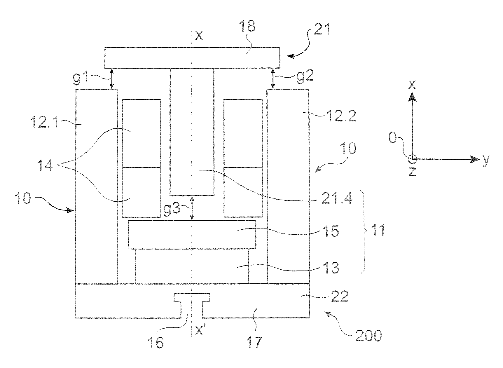
[0038] There follows a description of a first configuration for an actuator of the invention.

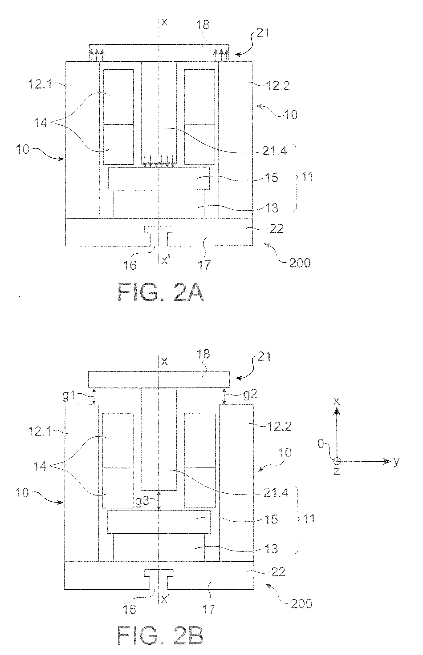
[0039] Reference is made to FIGS. 2A and 2B which are section views of a first embodiment of a magnetic actuator of the invention in two stable positions. The actuator is bistable. In FIG. 2A, it is in one stable position under the action of magnetic coupling forces, this position being the closed position. In FIG. 2B, it is in its other stable position, this time under the action of springs tending to separate the armature and the yoke, and developing a force that is greater than the force coming from the magnetic coupling in this position, this being the open position

[0040] The term “bistable” is used to mean that the actuator possesses two positions that are stable in the absence of current in the coil. It is possible to envisage an actuator that is not bistable. For example, provision could be made for the closed position to be held only providing some small residual current continues ...


PUM

PropertyMeasurementUnit
drive forceaaaaaaaaaa
magnetic fluxaaaaaaaaaa

Abstract

The invention relates to a magnetic actuator comprising at least one coil (14) surrounded by a magnetic circuit (10), the magnetic circuit possessing:
    • three legs (12.1, 12.2, 11), comprising two outer legs on either side of the coil (14) and an intermediate leg passing through the coil, these legs having no direct mechanical contact with one another; and
    • two facing end plates (17, 18) magnetically interconnecting the three legs (12.1, 12.2, 11). The magnetic circuit comprises a moving armature (21) comprising at least one of the end plates (18), and a stationary portion (200) including a yoke (22) having at least the other one of the end plates (17) and at least one permanent magnet (13), the permanent magnet (13) being placed at one end of the intermediate leg (11) beside the end plate (17) of the yoke (22). The invention is applicable to controlling medium-voltage and high-voltage circuit breaker vacuum chambers.

Description

TECHNICAL FIELD [0001] The present invention relates to a permanent-magnet magnetic actuator serving in particular for controlling vacuum “chambers” in medium-voltage or high-voltage circuit breakers. The invention also relates to a mechanism for controlling the contacts of one or more circuit breaker vacuum chambers, which mechanism is provided with such an actuator. STATE OF THE PRIOR ART [0002] Permanent-magnet magnetic actuators include so-called “plane geometry” actuators, e.g. the actuator described in patent application WO 96 / 32734 which is shown in section in FIG. 1. The term “plane geometry” means that the different sections on a plurality of substantially parallel planes of the magnetic circuit of the actuator are of substantially isometric, and superposable. This term “plane geometry” is used to distinguish from actuators in which the geometry is axially symmetrical. The drawback of actuators that are axially symmetrical, such as the actuator described in patent applicati...

Claims


Application Information

Patent Timeline
Patent Type & Authority Applications(United States)
IPC IPC(8): H01F7/08
CPCH01F7/081H01F7/122H01H33/6662H01F7/1623H01F7/1615
Inventor BONJEAN, MARCLEROY, PIERRE
Owner AREVA T&D
Why Eureka
Try Eureka