

Performance arrow vane
- Summary
- Abstract
- Description
- Claims
- Application Information
AI Technical Summary
Benefits of technology
Problems solved by technology
Method used
Image

Examples
Embodiment Construction
[0021] Throughout the following detailed description, like numerals are used to describe the same element of the present invention shown in multiple figures thereof.
[0022] The invention, Performance Arrow Vane, is a novel arrow vane which, through its design characteristics, generally promotes arrow flight stability and consistent flight with differing arrowhead weights, without requiring additional vane side or surface area.
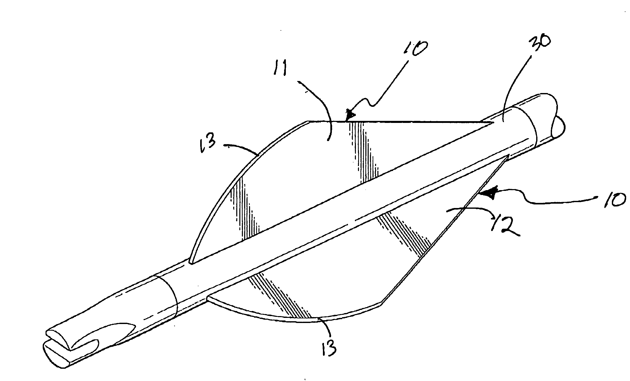
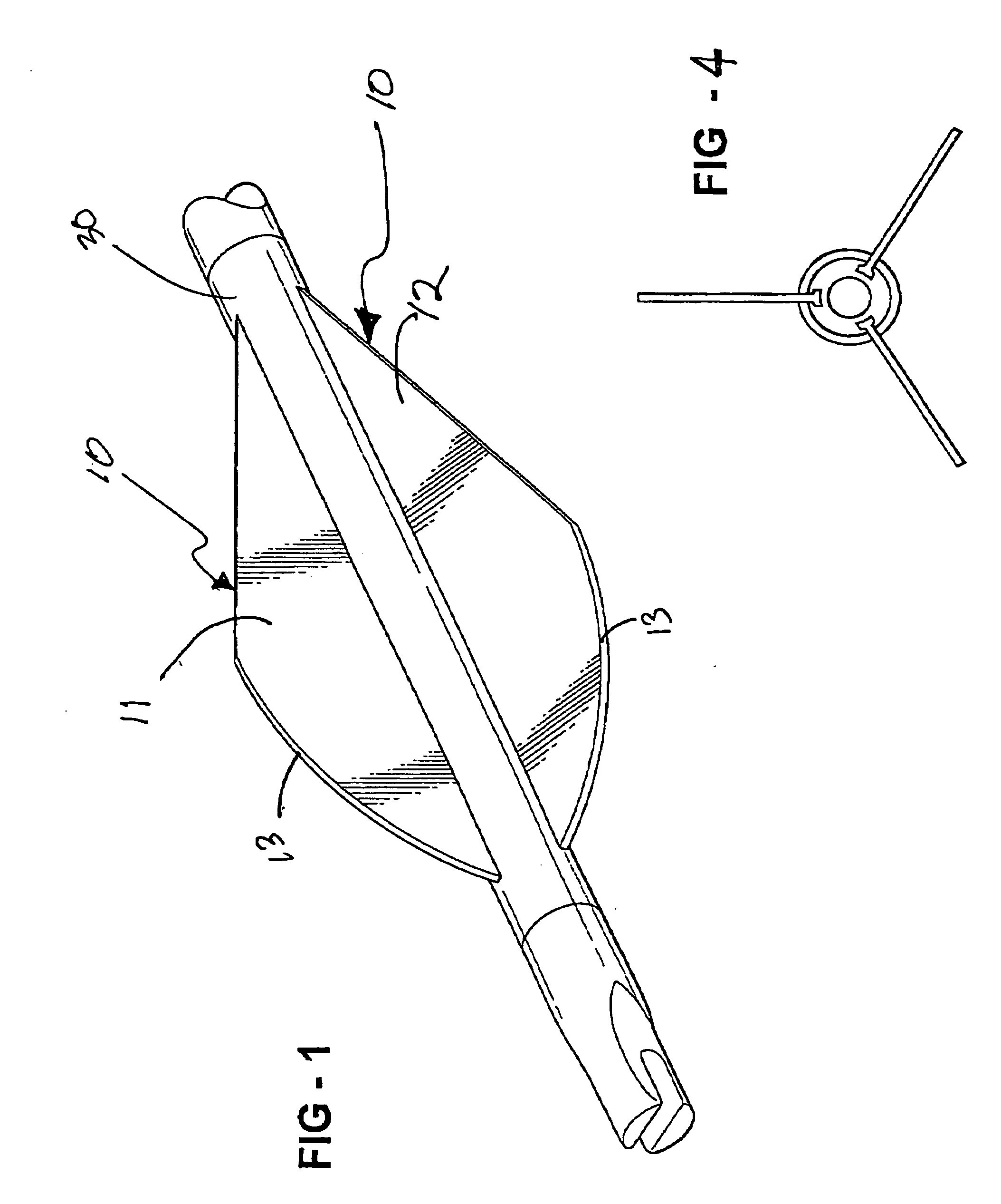
[0023] Broadly considered, the device Performance Arrow Vane is comprised of a primary vane member 10. Vane member 10 is substantially rigid to maintain its shape and position during arrow flight, but may be constructed of resiliently bendable material, synthetic or otherwise, which allow bending when contacted by force, but which will return to its original shape.
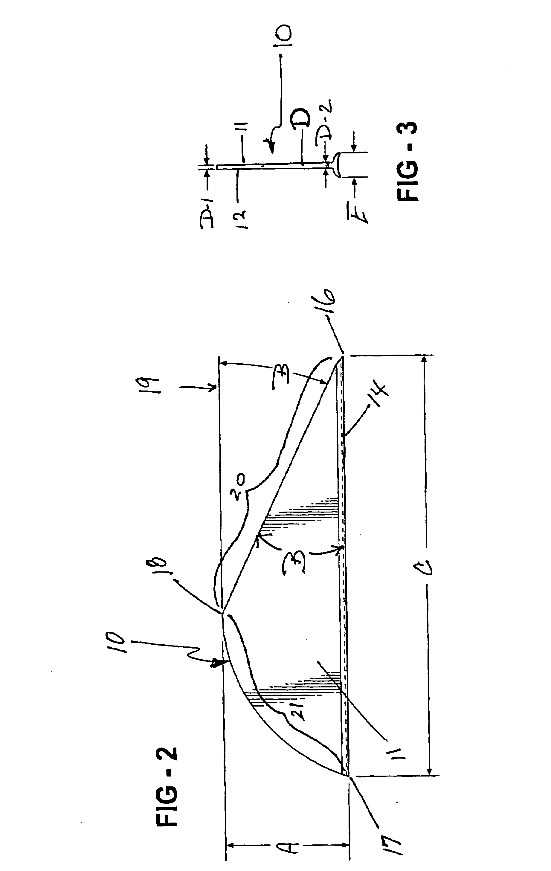
[0024] Vane member 10 has a front planar surface 11 and a rear planar surface 12, an upper edge 13 and a lower edge 14. As shown in FIG. 3, the planar surfaces 11 and 12 are spaced apart by width D ...
PUM
 Abstract
Description
Claims
Application Information