Quick-connect fitting

a technology of fast connection and fitting, which is applied in the direction of hose connection, fluid pressure sealing joints, pipe joints, etc., can solve the problems of damage to threads or other surface areas of test fittings, and achieve the effect of quick and easy coupling and preventing inadvertent loosening of the closur

Active Publication Date: 2007-08-02
CINCINNATI TEST SYST
View PDF1 Cites 18 Cited by
  • Summary
  • Abstract
  • Description
  • Claims
  • Application Information

AI Technical Summary

Benefits of technology

[0006] In one aspect in accordance with the principles of the present invention, a fitting that can quickly and easily be coupled to the outer surface of an inlet to a pipe system or a container comprises a housing having a base and a closure. The closure is coupled to the base to define a cavity within the housing. A resilient bushing is disposed within the cavity and is positioned between the closure and a piston that is slidably disposed in the cavity. The fitting has a first state wherein the inlet can be received within an inner diameter of the bushing through an aperture in the closure. The fitting can be actuated to a second condition wherein the piston axially compresses the resilient bushing against the closure, thereby causing the inner diameter of the bushing to expand radially inwardly to sealingly engage the outer surface of the inlet. When the inlet is sealingly engaged by the resilient bushing in the second condition, fluid may be admitted to the inlet through a fluid passage in the housing.

Problems solved by technology

Some of these fittings utilize collets or other clamping devices that can crimp, mar, or otherwise damage the surface of a pipe, conduit or other inlet structure to which the fitting is connected.
Prior fittings which include locking mechanisms often utilize set screws or other devices in a manner that damages threads or other surface areas of the test fitting.

Method used


Image

  • Quick-connect fitting
  • Quick-connect fitting
  • Quick-connect fitting

Examples


Embodiment Construction

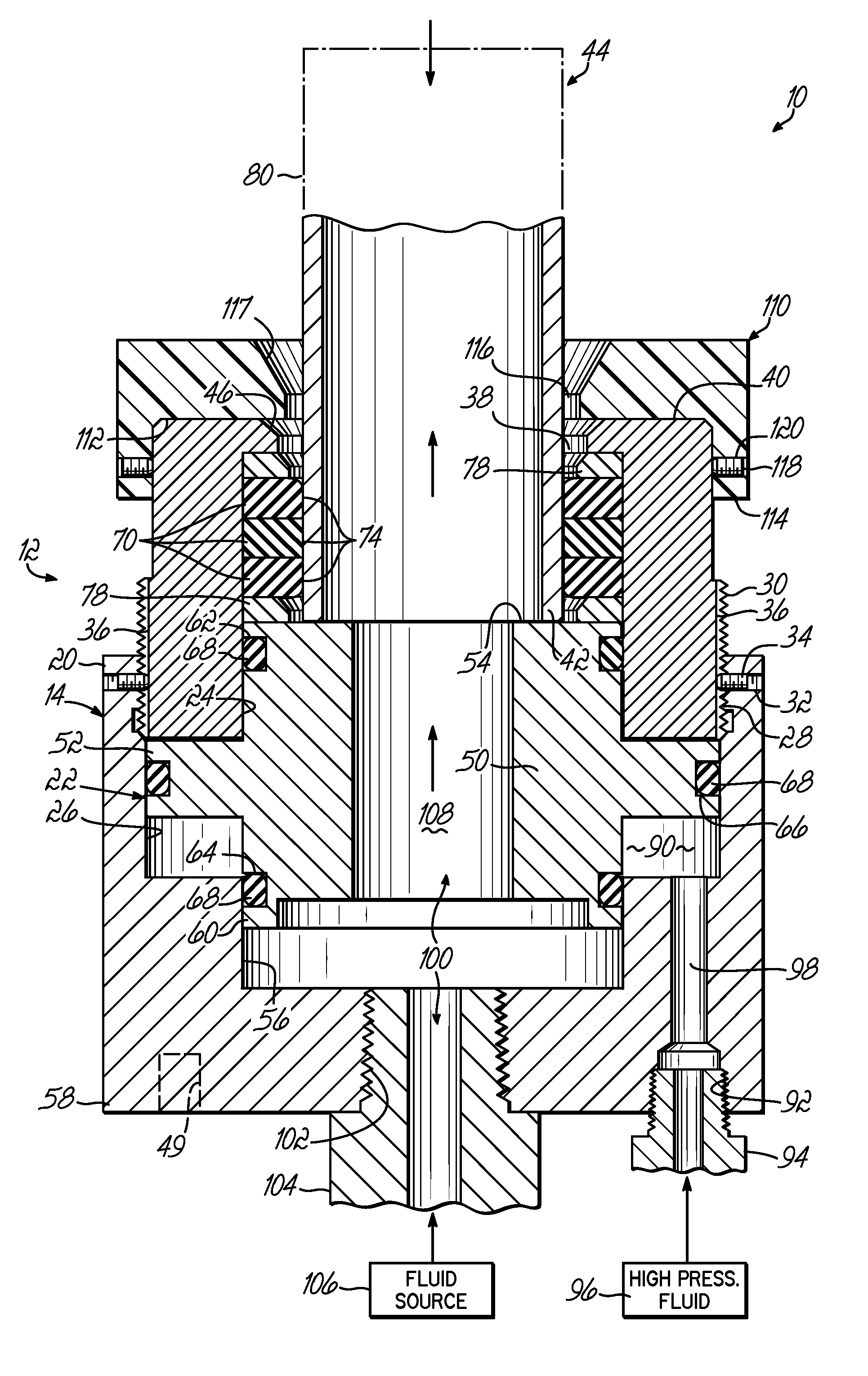
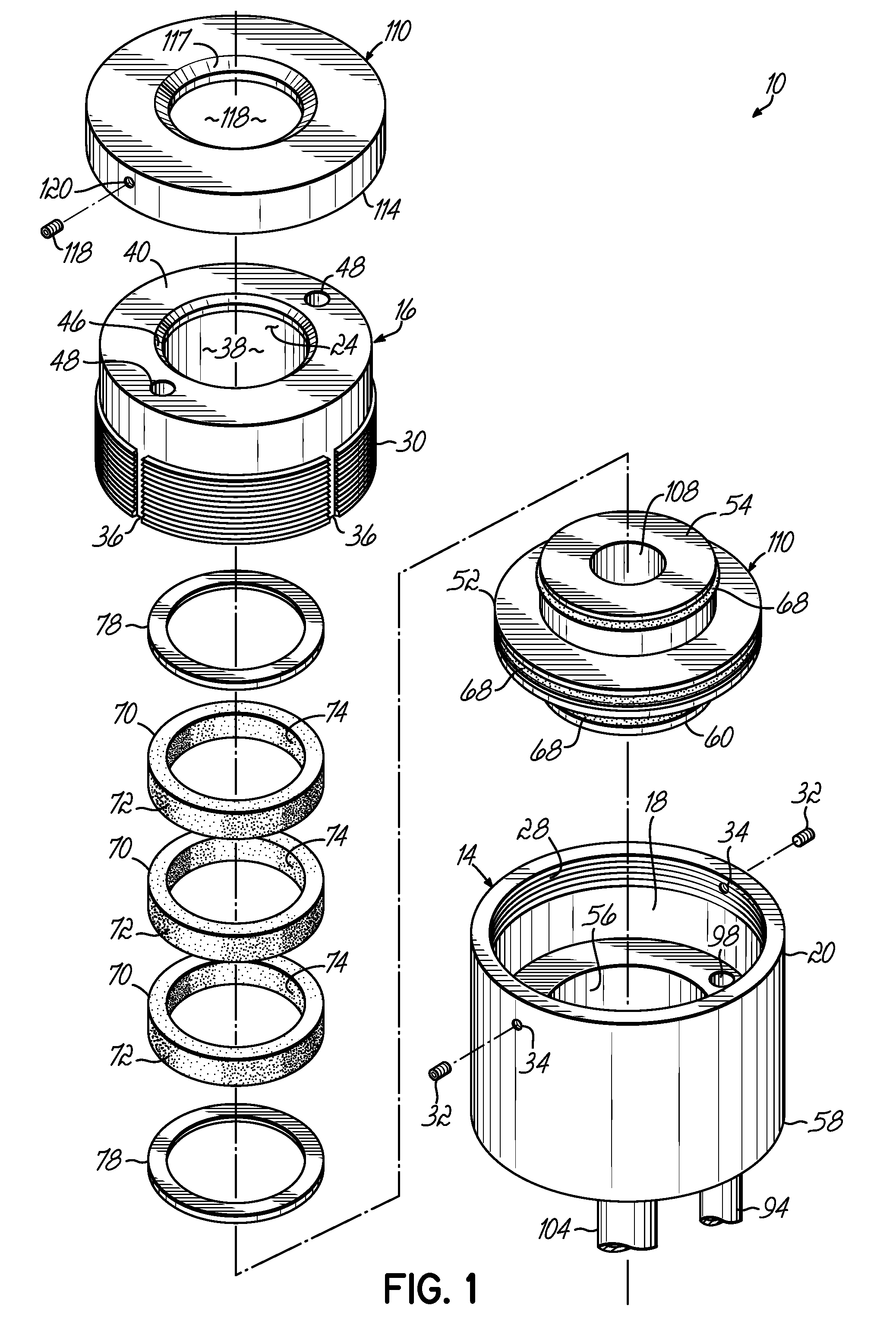
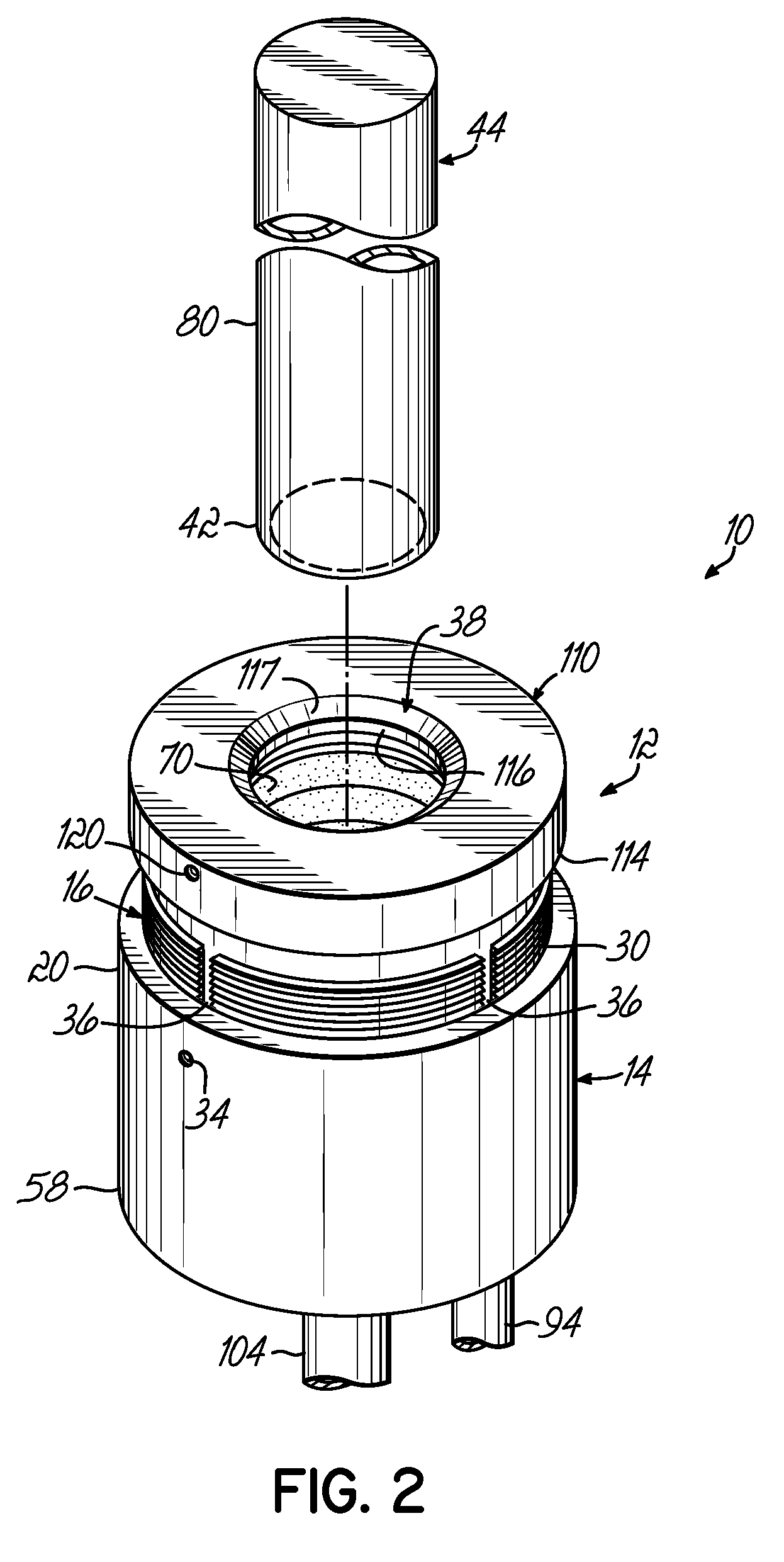
[0017]FIGS. 1, 2 and 3A depict an exemplary fitting in accordance with the principles of the present invention for quick and easy coupling to the inlet of a piping system or container to facilitate filling the system or container with fluid. The fitting 10 includes a housing 12 having a base 14 and a closure 16 coupled to the base 14. In the embodiment shown, the base 14 comprises a generally cylindrical body having a recess 18 formed into a first end 20 for receiving a piston 22, as will be described in more detail below. The closure 16 also has a generally cylindrical shape and has a corresponding recess 24 formed into a lower portion thereof, whereby the base 14 and closure 16 define an internal cavity 26 within housing 12 when coupled together. In the embodiment shown, base 14 includes internal threads 28 formed at the open first end 20. The closure 16 is received within the open first end 20 of base 14 and includes externally formed threads 30 corresponding to the internal thre...


PUM


Abstract

A fitting for sealing against the outer surface of an inlet includes a housing comprising a base and a closure defining a cavity within the housing. A resilient bushing is disposed within the cavity and is positioned between the closure and a piston slidably disposed in the cavity. The fitting has a first condition wherein the inlet can be received within an inner diameter of the bushing through an aperture in the closure. The fitting can be actuated to a second condition wherein the piston axially compresses the resilient bushing against the closure, thereby causing the inner diameter of the bushing to expand radially inwardly to sealingly engage the outer surface of the inlet. When the inlet is sealingly engaged by the resilient bushing in the second condition, fluid may be admitted to the inlet through a fluid passage in the housing.

Description

FIELD OF THE INVENTION [0001] The present invention relates generally to fittings for connecting a fluid supply to an inlet, and more particularly to a quick-connect fitting configured to engage the outer surface of a pipe or conduit. BACKGROUND OF THE INVENTION [0002] Fittings that can be connected to and disconnected from pipes or conduits are useful for filling and leak testing various mechanical systems having a piping network or other configurations of passages adapted to transport fluids, such as refrigeration systems, hydraulic lines, automotive fuel rails and fuel lines, automotive intake and exhaust manifolds, and other systems. In other applications, fittings may be used to facilitate filling containers with fluid without leak testing the containers. When many containers are to be filled in succession, or when it is desired to leak test several fluid carrying systems, the fitting should be capable of quick and easy connection and disconnection, while maintaining good seali...

Claims


Application Information

Patent Timeline
Patent Type & Authority Applications(United States)
IPC IPC(8): F16L17/00
CPCF16L37/62
Inventor MCBEE, JEFFREY W.BERBERICH, DEAN A.THUNGA, MITRA
Owner CINCINNATI TEST SYST
Why Eureka
Try Eureka