Print head

a printing head and jet-type technology, applied in printing and other directions, can solve the problems of inability to stably eject ink, inability to hold ink in good condition in the nozzle, and more likely to break the meniscus, and achieve the effect of stably ejecting ink droplets and large volum

Inactive Publication Date: 2007-08-02
COPYER
View PDF1 Cites 11 Cited by
  • Summary
  • Abstract
  • Description
  • Claims
  • Application Information

AI Technical Summary

Benefits of technology

[0018]The present invention has been accomplished with a view to overcoming the above-mentioned problems and it is an object of this invention to provide a print head capable of stably ejecting ink droplets of large volume without being influenced by negative pressure variations and drive conditions.

Problems solved by technology

Among the special inks there are ones that have higher viscosities than those of ordinary inks and are difficult to eject stably.
This in turn makes the meniscus more likely to be broken when subjected to variations in a negative pressure in the ink supply system, giving rise to a problem that the ink may not be held in good condition in the nozzle 5.
That is, if the meniscus is broken prior to an ejection operation, a situation arises where the heater is energized with no ink or only an insufficient amount of ink left in the nozzle 5, causing a faulty ejection of ink droplets.
Further, the small capillary attraction force in the nozzle 5 causes another problem.
When the amount of ink in the ink tank, that supplies ink to the print head H1, decreases and the resultant negative pressure increases, an ink refilling to the nozzle becomes slow.
As a result, the ink ejection becomes unstable, and a printed result gets hoarse.
The conventional print head H1, as described above, has two conflicting problems that an increase in the opening area of the nozzle opening 3 degrades a meniscus maintaining performance and a nozzle refilling performance and that, conversely, a reduction in the nozzle opening area makes it difficult to secure a sufficient volume of ink droplet to be ejected.
So, these ink droplets do not merge together to form a single droplet and may degrade the quality of a printed image.
Particularly, in the case of the print head of FIG. 13, the individual, separated nozzle openings are elongate rectangles in shape, making the direction in which the ink droplets are ejected from the nozzle openings unstable, with the result that the droplets hardly merge into a single droplet.
So, if the ink droplets expelled merge together, the united ink droplet as a whole is elongate, making the direction of the flying ink droplet unstable.

Method used


Image

  • Print head
  • Print head
  • Print head

Examples


first embodiment

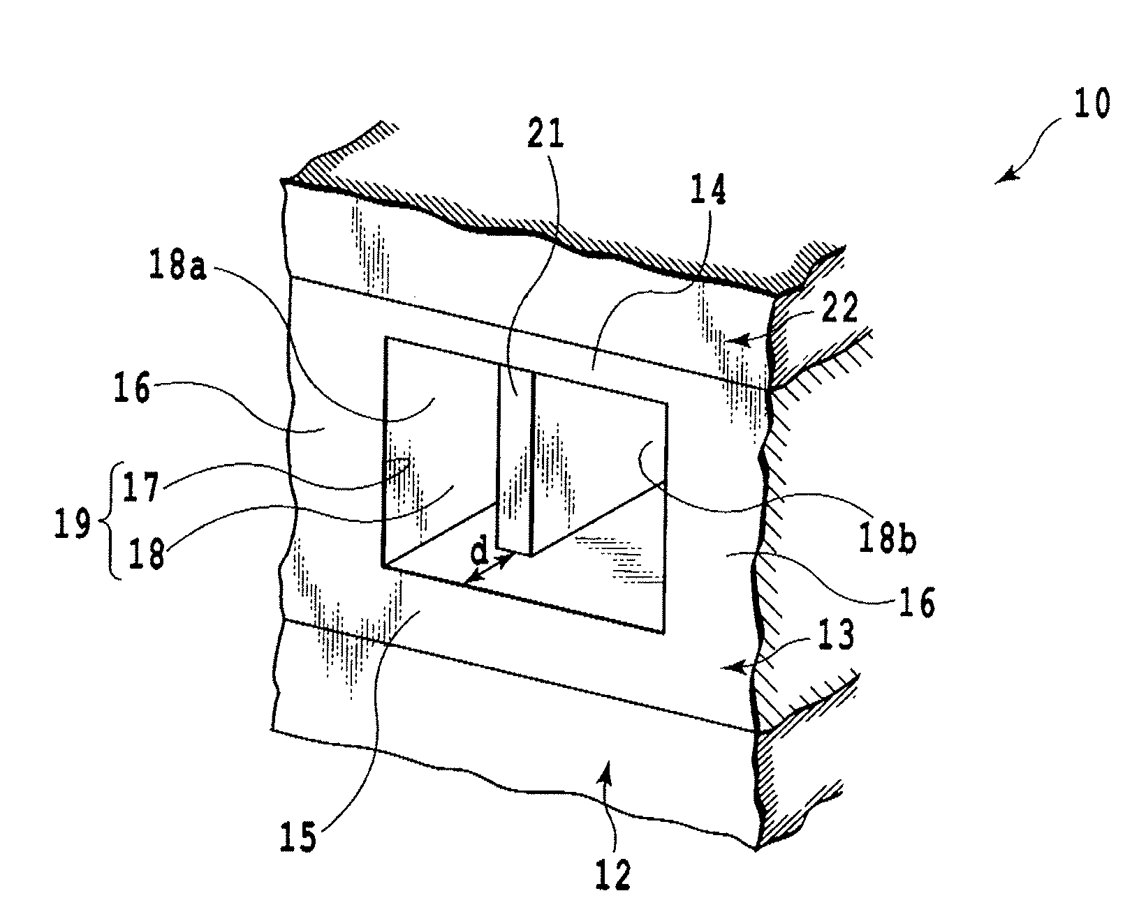
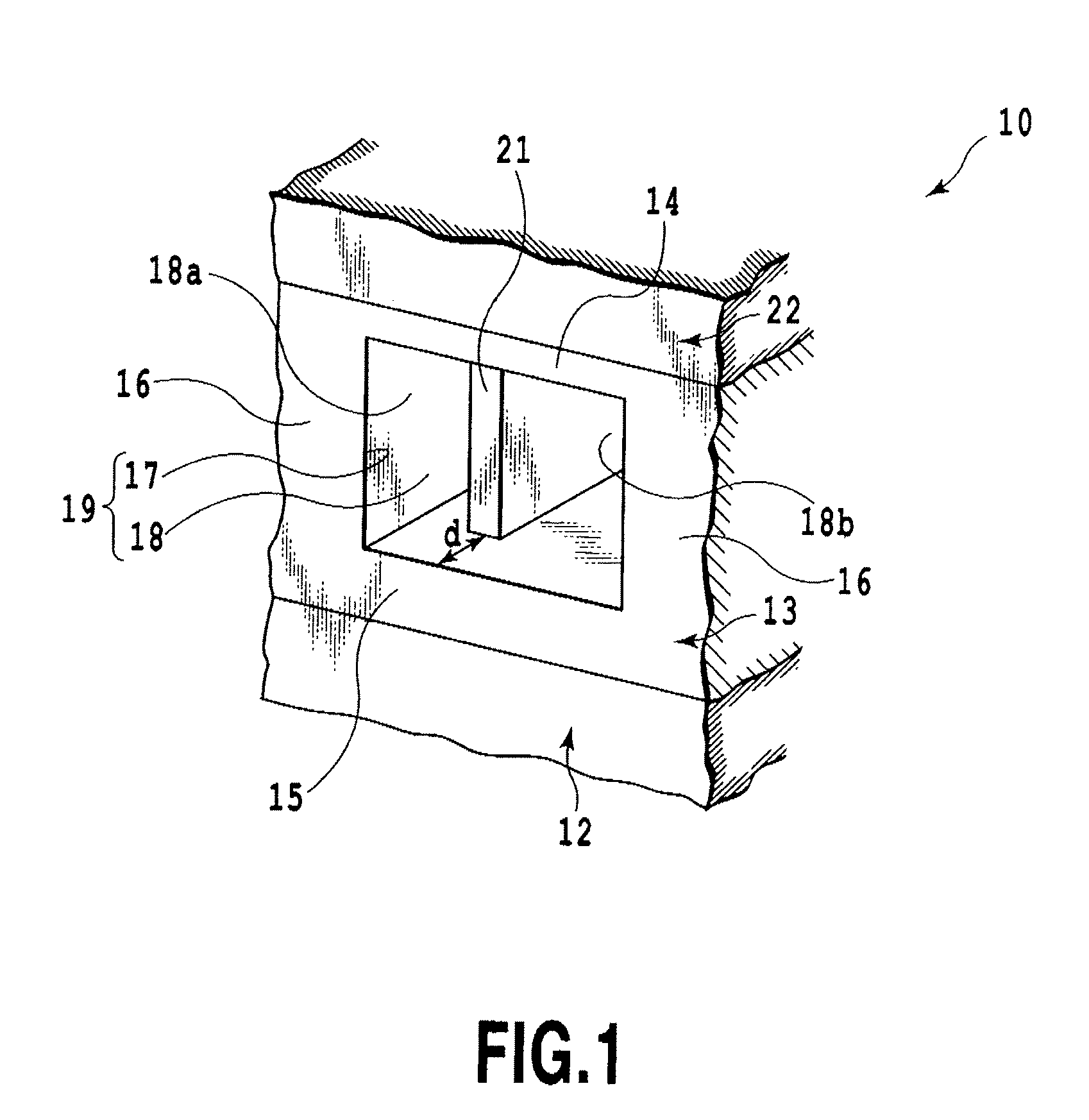
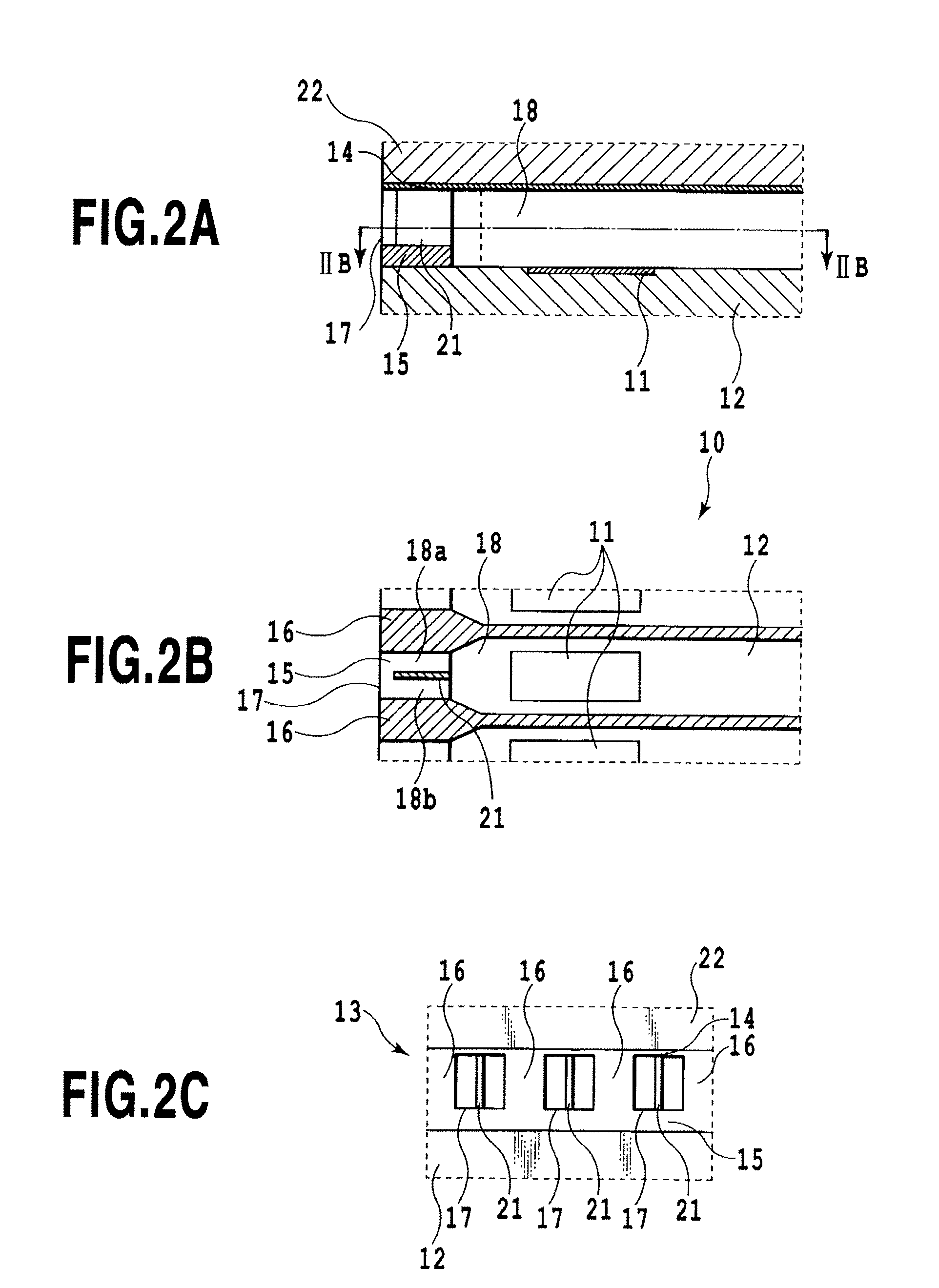
[0046]FIG. 1 is a perspective view schematically showing a construction of a nozzle opening and its associated components in a print head 10 according to a first embodiment of this invention used in an ink jet printing apparatus. FIG. 2A is a longitudinally sectioned side view showing a construction of nozzle openings and liquid paths communicating with them in the print head 10. FIG. 2B is a cross-sectional view taken along the line B-B of FIG. 2A. FIG. 2C is a front view of FIG. 2A.

[0047]As shown in FIG. 1 and FIGS. 2A to 2C, the print head 10 has a heater board 12 with heaters 11 to heat ink and form a bubble to expel an ink droplet, a nozzle forming member 13 installed on the heater board 12, and a top plate 22 placed on the nozzle forming member 13. End faces of these members are formed to lie in the same plane.

[0048]A nozzle opening forming surface, the end face of the nozzle forming member 13, is formed with ink ejecting, rectangular nozzle openings 17 at predetermined interv...

second embodiment

[0055]In the print head 10 shown in FIG. 1 to FIG. 3E, the dividing portion 21 is shaped like a flat plate of uniform thickness. The dividing portion 21, however, may be constructed in other shapes than that shown in FIG. 1 and FIGS. 3A to 3E. For example, it may be constructed in shapes of a second embodiment of this invention as shown in FIG. 4 or FIG. 5.

[0056]In a print head 10a shown in FIG. 4, there is provided a tapered dividing portion 22 whose thickness decreases toward the nozzle opening 17. The taper of the dividing portion allows the inks that have flowed through the two divided paths 18a, 18b separated by the dividing portion 22 to merge together easily as they are ejected from the nozzle opening 17, assuring a more stable ink ejection,

[0057]Further, like a dividing portion 23 in a print head 10b of FIG. 5, the dividing portion may also be provided with a tapered portion 23a that reduces its thickness toward the nozzle opening 17 and a tapered portion 23b that reduces it...

third embodiment

[0058]Next, a third embodiment of this invention will be described.

[0059]FIG. 6A is a longitudinally sectioned side view schematically showing a construction of a print head according to the third embodiment of this invention. FIG. 6B is a cross-sectional view taken along the line B-B of FIG. 6A. FIG. 6C is a front view of FIG. 6A.

[0060]The print head 10d in the third embodiment of this invention is also similar in the basic construction to the first embodiment. That is, on the heater board 12 having heaters 11 to heat ink and form bubbles for ejecting ink droplets, there is provided a nozzle forming member 13 that has nozzles formed therein, each comprising a nozzle opening 17 for ejecting ink and a liquid path 18 communicating with the nozzle opening. A top plate 22 is placed on the nozzle forming member 13.

[0061]The nozzle forming member 13 is also formed with a planar portion 14, sidewalls 16, a bottom portion 15 and dividing portions 21, all defining the nozzle openings. The di...


PUM


Abstract

It is an object of this invention to provide a print head which can stably eject ink droplets of large volume without being influenced by negative pressure variations in an ink supply source or by drive conditions. To this end the ink jet print head of this invention includes a plurality of nozzle openings to eject ink, a plurality of liquid paths communicating with these nozzle openings, and energy generation portion to eject ink supplied to each liquid path from each nozzle opening in the form of an ink droplet. In a part of each liquid path, a dividing portion to divide the liquid path into a plurality of paths is installed inward of the nozzle opening.

Description

[0001]This application claims the benefit of Japanese Patent Application No. 2006-026349, filed Feb. 2, 2006, which is hereby incorporated by reference herein in its entirety.BACKGROUND OF THE INVENTION[0002]1. Field of the Invention[0003]The present invention relates to an ink jet print head having a plurality of nozzles and adapted to eject ink droplets from its nozzles, and more particularly to a print head that ejects ink droplets of relatively large volume.[0004]2. Description of the Related Art[0005]Ink jet printing apparatus perform printing by ejecting ink droplets from nozzles arrayed in their print head to directly land on a print medium. This allows the printing operation to be performed with low noise and obviates the need for special processing such as development. The ink jet printing apparatus therefore have advantages of being able to be constructed at low cost and in small size and to realize a color printing capability easily. Particularly with an ink jet printing ...

Claims


Application Information

Patent Timeline
Patent Type & Authority Applications(United States)
IPC IPC(8): B41J2/05
CPCB41J2/14064B41J2/14048
Inventor FUJIWARA, YUKI
Owner COPYER
Why Eureka
Try Eureka