Ruggedized electronics enclosure

a technology of electronics enclosures and enclosures, applied in the direction of cooling/ventilation/heating modifications, printed circuit board receptacles, modifications by conduction heat transfer, etc., can solve the problems of difficult if not impossible upgrade to the latest technology, custom equipment is often significantly more expensive than commercial systems, and cot systems

Inactive Publication Date: 2007-08-02
KEHRET WILLIAM E +1
View PDF22 Cites 13 Cited by
  • Summary
  • Abstract
  • Description
  • Claims
  • Application Information

AI Technical Summary

Benefits of technology

[0018] The present invention overcomes the limitations and disadvantages of conventional electronics enclosures used in harsh operating environments. In one embodiment, the invention provides protection from destructive shock events and destructive vibration events without need of external mechanical isolation.
[0019] In one embodiment, the electronics enclosure includes a top compartment for housing the electronic circuit, and a cooling assembly attached thereto. The top compartment may be sealed to further protect the electronic circuit from moisture and unwanted particles in the air. The cooling assembly includes a rigid truss plate structure which forms a structural member for rigidifying the enclosure, and also forms an efficient heat radiator for removing heat from the electronic circuit. The truss plate structure achieves it's high strength to weight ratio in a manner similar to conventional “honey-comb” or sandwich structures. The truss plate structure converts bending mode forces, applied to opposing plates, into compression and extension mode forces. However, unlike conventional “honey-comb” or sandwich constructions, the present invention provides ducts or passage ways through which cooling air (or other cooling fluid) is allowed to flow to aid in the efficient removal of heat from the top compartment. In an alternate embodiment, the truss plate structure is a honey-comb truss structure that provides passages through which cooling air (or other cooling fluid) is allowed to flow.
[0020] In one embodiment, the rigid truss plate structure is formed from a passive radiator coupled between a heat spreader plate and a bottom plate. The heat spreader plate also forms the bottom of the top enclosure and provides both mechanical and thermal coupling between the top compartment and the cooling assembly. In one embodiment, the passive radiator may be comprised of a corrugated fin. In another embodiment, the passive radiator is comprised of triangularly shaped fins (an A-frame structure). Both the corrugated fin and the triangular fin structure may provide additional protection against destructive shear and twisting of the enclosure. In another embodiment, the passive radiator is comprised of a pin-style heatsink. In one embodiment the pin-style heatsink is arranged according to a pin density pattern to create a turbulence gradient for the cooling assembly.

Problems solved by technology

Examples of such conditions include excessive moisture, salt, heat, vibrations, and mechanical shock.
While effective in surviving the environment, custom equipment is often significantly more expensive than commercial systems, and is typically difficult if not impossible to upgrade to the latest technologies.
While COTS systems have allowed the military to reduce the cost of equipment and to make more frequent upgrades to existing equipment, there are inherent disadvantages to COTS systems.
Both approaches suffer from added complexity, size, weight and cost.
Taken together, these design considerations drastically increase the cost and complexity of such an enclosure.
Keeping costs down to a minimum is counter to the requirements of making a system robust enough to survive a military environment.
In practice, this is not easily achieved, especially when using larger, and heavier computer systems.
Thus, the idea of completely isolating a commercial system from the rigors of the military environment is difficult to achieve and adds a large cost premium because the rack is the item being modified.
The current solution to supporting COTS technology in a military environment described above, adds significant complexity to the system.
Two of the most difficult conditions to design for are vibration and mechanical shock.
Mechanical shock and vibration may over time destroy electronic equipment by deforming or fracturing enclosures and internal support structures and by causing electrical connectors, circuit card assemblies and other components to fail.
In military applications, as well as in commercial avionics and the automotive industry, electronics must be able to operate while being subjected to constant vibrational forces generated by the vehicle engines, or waves, as well as being subjected to sudden, and often drastic, shocks.
While providing some protection from shock and vibration, the conventional ruggedized enclosure operating alone cannot provide adequate protection for mission-critical electrical components and circuits.
There are several drawbacks to using the mechanically isolated cocoon 100.
Thus, there is still a significant chance for failure within the system.
However, while more effective in protecting the equipment from mechanical shock, these ruggedized enclosures 110 work only when the shock isolation system is carefully integrated with the included systems.
Thus, the cost and complexity of such a system are significantly higher when compared to a commercial system using similar electrical components.

Method used


Image

  • Ruggedized electronics enclosure
  • Ruggedized electronics enclosure
  • Ruggedized electronics enclosure

Examples


Embodiment Construction

[0033] A preferred embodiment of the present invention is now described with reference to the figures where like reference numbers indicate identical or functionally similar elements. Also in the figures, the left most digit(s) of each reference number correspond(s) to the figure in which the reference number is first used.

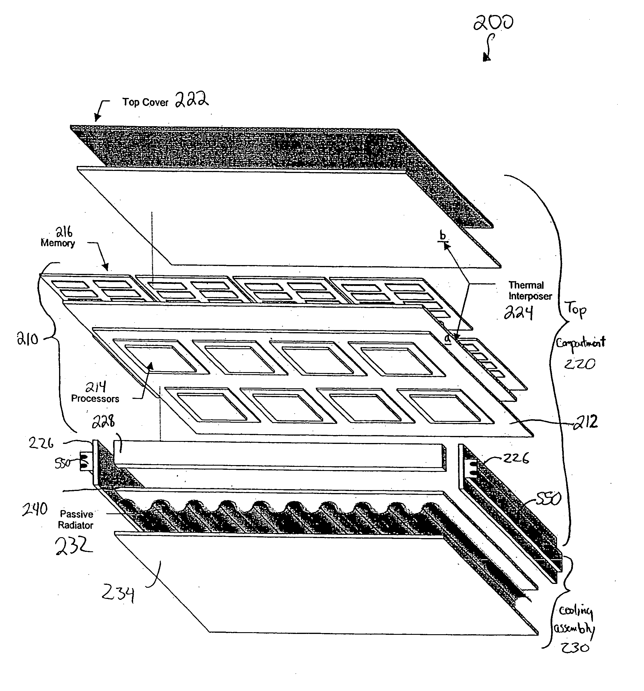
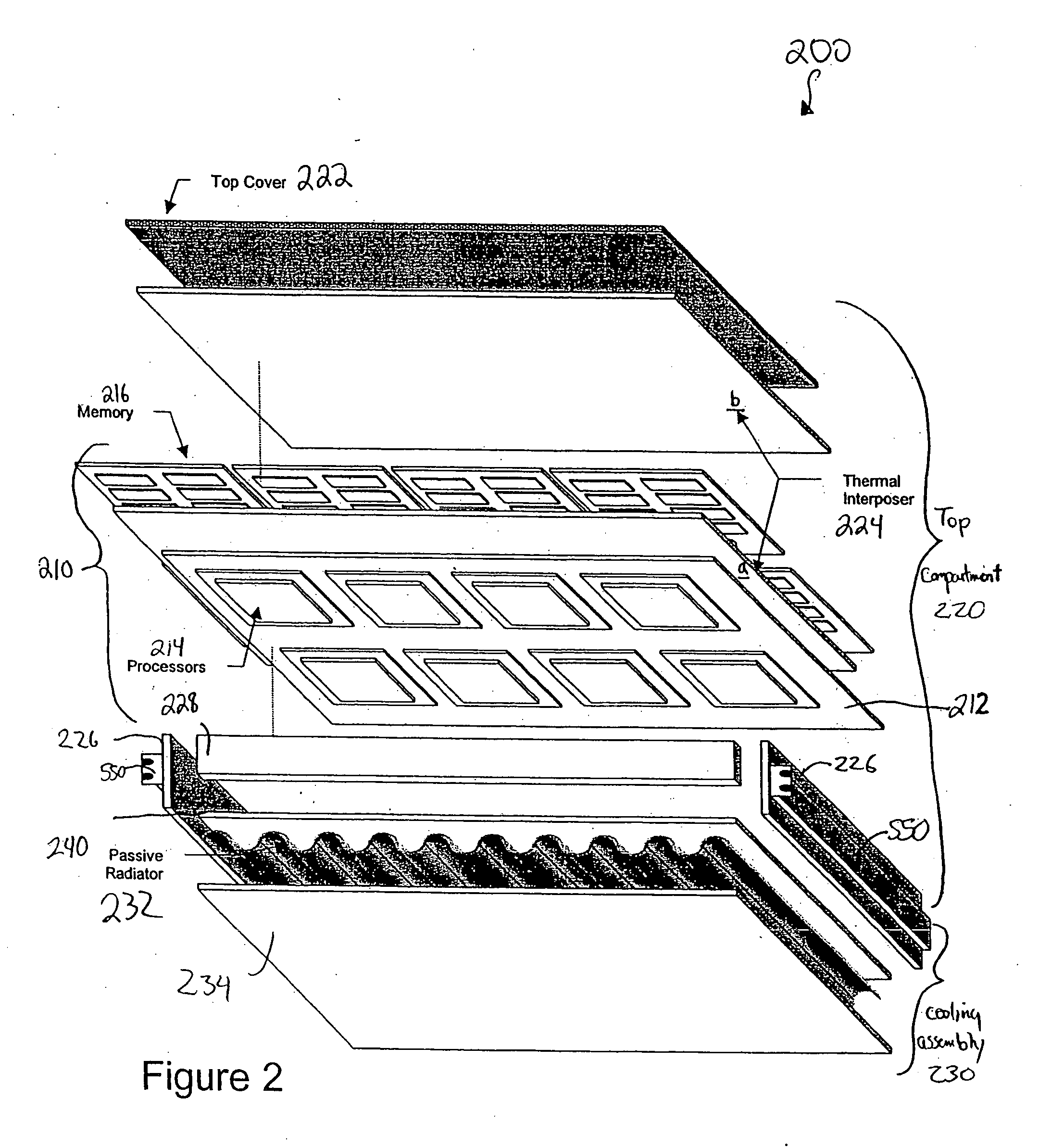
[0034] The present invention relates to a ruggedized electronics enclosure for protecting electronic circuits that must be able to survive and operate under harsh conditions such as those in military and automotive environments. The enclosure must be able to protect the electronic circuits from severe vibration and shock, heat, moisture, dust particulate, and various other adverse conditions. Throughout this description, the word “destructive” will be used to indicate a force or event which may cause the enclosure or the electronic circuit to fail after a single occurrence of the event, or after repeated occurrences of the event between maintenance intervals. Spe...


PUM


Abstract

The present invention relates to a ruggedized enclosure for housing and protecting electronic circuits. The enclosure utilizes a top compartment for housing the circuit and a cooling assembly rigidly coupled to the top compartment. The cooling assembly utilizes a passive radiator to form a rigid truss plate structure. The truss plate structure rigidifies the enclosure helping to protect the enclosure and circuit from destructive shock events and destructive vibration events. The cooling assembly further provides an efficient heat exchange for removing heat from the electronic circuit. A method for protecting an electronic circuit utilizing a rigid truss plate structure is also provided.

Description

RELATED APPLICATION [0001] This application is a continuation of U.S. patent application Ser. No. 10 / 850,523, entitled “Ruggedized Electronics Enclosure”, that was filed on May 19, 2004, which is a continuation of U.S. patent application Ser. No. 10 / 232,915, entitled “Ruggedized Electronics Enclosure,” that was filed on Aug. 30, 2002.BACKGROUND OF THE INVENTION [0002] 1. Field of the Invention [0003] This invention is related to enclosures for electronic circuits and particularly to ruggedized enclosures for use in installations subjected to hostile environments including destructive shock events and destructive vibration events. In one embodiment, the invention may operate without requiring additional mechanical isolation. [0004] 2. Description of the Related Art [0005] Conventional ruggedized electronics enclosures are often employed in military applications. The environments in which military electronic circuits must be able to operate typically present conditions outside of a co...

Claims


Application Information

Patent Timeline
Patent Type & Authority Applications(United States)
IPC IPC(8): H05K7/20
CPCH05K7/1434H05K7/20254H05K7/20509H05K7/20445H05K7/20418
Inventor KEHRET, WILLIAM E.SMITH, DENNIS H.
Owner KEHRET WILLIAM E
Why Eureka
Try Eureka