Network system and node redundancy method of network system
- Summary
- Abstract
- Description
- Claims
- Application Information
AI Technical Summary
Benefits of technology
Problems solved by technology
Method used
Image
Examples
Embodiment Construction
[0057]Embodiments of the present invention will now be described. These embodiments however shall not be for limiting the technical scope of the present invention.
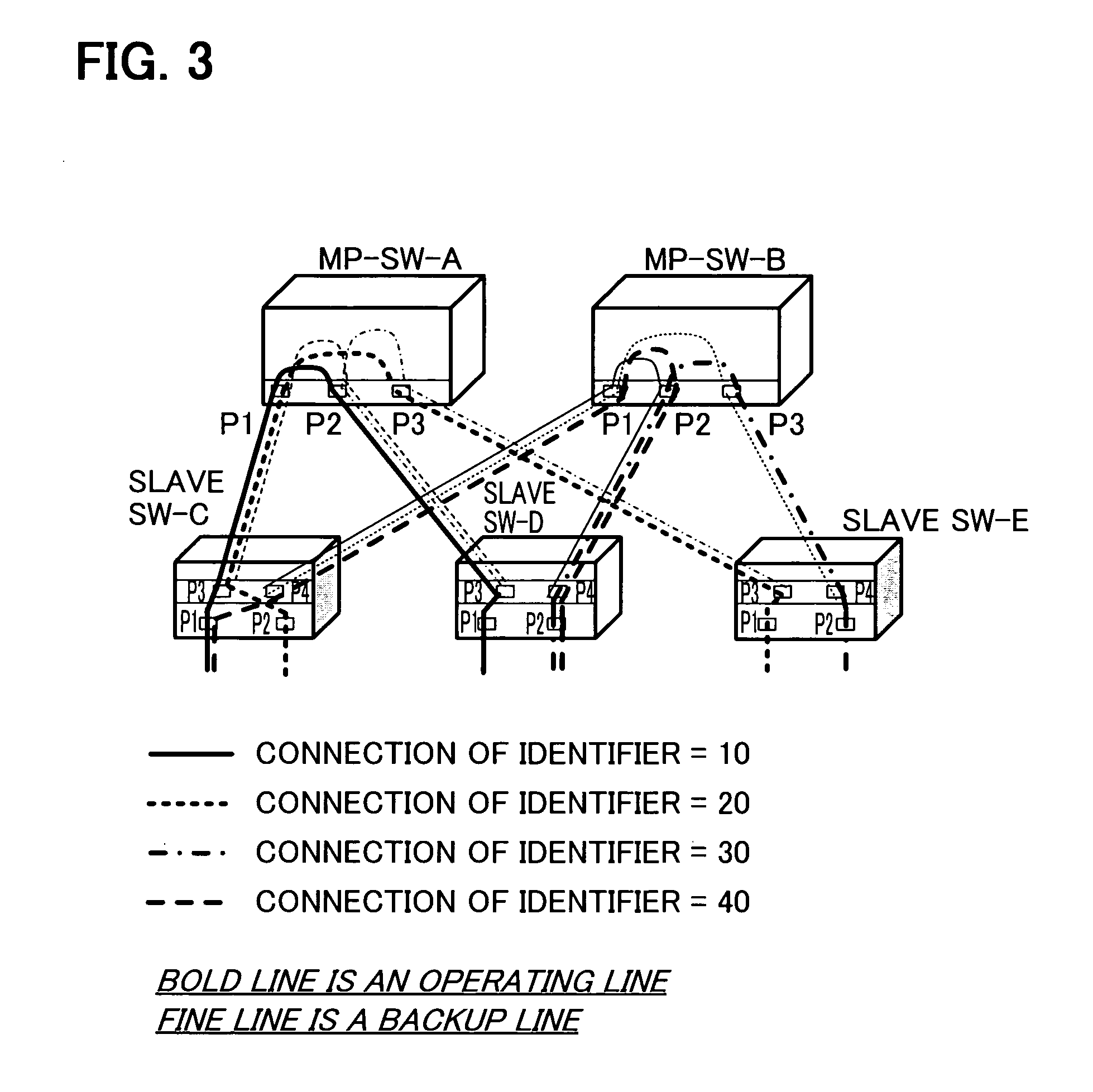
[0058]FIG. 8 is a diagram depicting the network system according to a present embodiment. The network configuration in FIG. 8, which is the same as the configuration in FIG. 3, is a star type network system having a plurality of multi-point switches MP-SW (master nodes), and a plurality of MP-SWs which form a redundancy configuration. In two master nodes MP-SW-A and MP-SW-B, logical connections with identifiers 10, 20 and 40 are set to port 1, logical connections with identifiers 10, 30 and 40 are set to port 2, and logical connections with identifiers 20 and 30 are set to port 3, and three slave nodes (slave SW-C, slave SW-D and slave SW-E) select a data frame transmission destination MP-SW, thus the redundancy of MP-SW is implemented.
[0059]At this time, in the slave SW, the logical connection connected to MP-SW-A is an o...
PUM
 Abstract
Description
Claims
Application Information
 - R&D
- Intellectual Property
- Life Sciences
- Materials
- Tech Scout
- Unparalleled Data Quality
- Higher Quality Content
- 60% Fewer Hallucinations
Browse by: Latest US Patents, China's latest patents, Technical Efficacy Thesaurus, Application Domain, Technology Topic, Popular Technical Reports.
© 2025 PatSnap. All rights reserved.Legal|Privacy policy|Modern Slavery Act Transparency Statement|Sitemap|About US| Contact US: help@patsnap.com


