Airflow control system

a technology of airflow control and ventilation, which is applied in ventilation systems, lighting and heating apparatus, heating types, etc., can solve the problems of damage to the environmental control unit, the inability to adjust the amount of ventilation, and the need to readjust all ventilation

Inactive Publication Date: 2007-08-02
ADAPTIVE
View PDF17 Cites 50 Cited by
  • Summary
  • Abstract
  • Description
  • Claims
  • Application Information

AI Technical Summary

Benefits of technology

[0008] The present invention is generally directed to an apparatus and a method for controlling an environment in a location. In one aspect, an apparatus for controlling an environmental condition in a location is provided. The apparatus includes a flow control device, wherein the flow control device is connectable to an environmental control unit via a conduit. The flow control device includes a flow restriction member configured to selectively control an airflow into the location and a controller member configured to autonomously actuate the flow restriction member based upon the environmental condition in the location.
[0009] In another aspect, a method for controlling an environmental condition in a first location and a second location is provided. The method includes placing a first flow control device within the first location and a second flow control device within the second location. The method further includes controlling the environmental condition in each location by autonomously controlling airflow through each flow control device. The method also includes sending a signal from the first flow control device to the second flow control device via a duct system that interconnects the flow control devices. Additionally, the method includes detecting the signal in the second flow control device and adjusting the airflow through the second flow control device.
[0010] In a further aspect, a system for controlling an environmental condition in a first location and a second location is provided. The system includes a first flow control device and a first sensor member disposed within the first location, the first sensor member configured to sense and send environmental data regarding the first location to the first flow control device. Additionally, the system includes a second flow control device and a second sensor member disposed within the second location, the second sensor member configured to sense and send environmental data regarding the second location to the second flow control device, wherein each flow control device includes a flow restriction member and a controller member configured to autonomously actuate the flow restriction member.
[0011] In yet a further aspect, a method for controlling an environmental condition in a location is provided. The method includes placing a flow control device within the location, wherein the flow control device is connected to an environmental control unit via a conduit. The method further includes comparing the environmental condition to an environmental condition parameter. Additionally, the method includes controlling the environmental condition in the location by autonomously controlling airflow through the flow control device based upon a difference in the environmental condition and the environmental condition parameter.

Problems solved by technology

These air vents provide a limited ability to adjust the amount of airflow into a room or area, the air coming from a central environmental control unit, such as a furnace, central air conditioner, or dehumidifier.
This usually leads to the need to readjust all vents if any one of the vents is opened or closed, a process which may require several iterations to perfect, and then only for the specific conditions at the time the adjustment was made.
Further, if one overly restricts airflow by closing too many vents, damage to the environmental control unit may occur.
This can be an inconvenience especially in situations where a user wishes to open or close a vent at multiple times during the day to account for changes in solar influx or room use pattern.
A further complication occurs when a user wishes to boost the heating or cooling in a specific room.
A further restriction of these devices is that they are operated independently, but still affect each other as it relates to cooling, heating, humidity, or to control complex multi-room issues.

Method used


Image

  • Airflow control system
  • Airflow control system
  • Airflow control system

Examples


Embodiment Construction

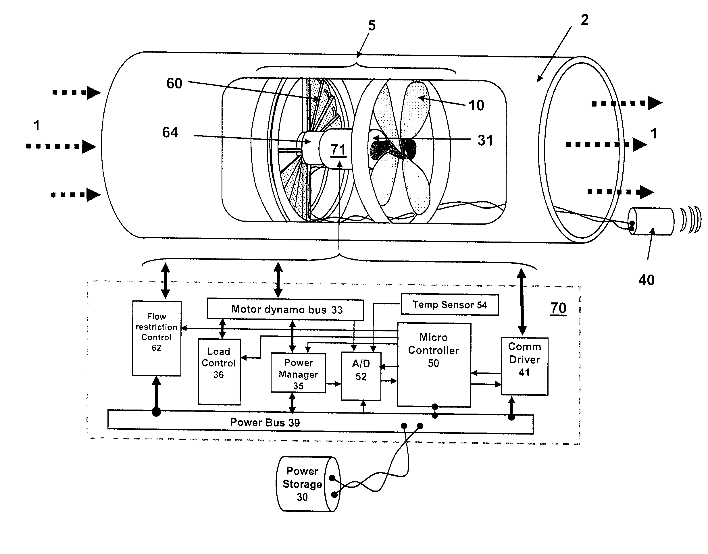
[0043] The present invention is generally directed to a method and apparatus for controlling the flow of a fluid through a heating, ventilating, and air conditioning system. Various terms as used herein are defined below. To the extent a term used in a claim is not defined below, it should be given the broadest definition persons in the pertinent art have given that term, as reflected in printed publications and issued patents. In the description that follows, like parts are marked throughout the specification and drawings with the same number indicator. The drawings may be, but are not necessarily to scale, and the proportions of certain parts have been exaggerated to better illustrate details and features of the invention. One of ordinary skill in the art of a heating, ventilating, and air conditioning system will appreciate that the embodiments of the invention can and may be used in various types of flow control systems.

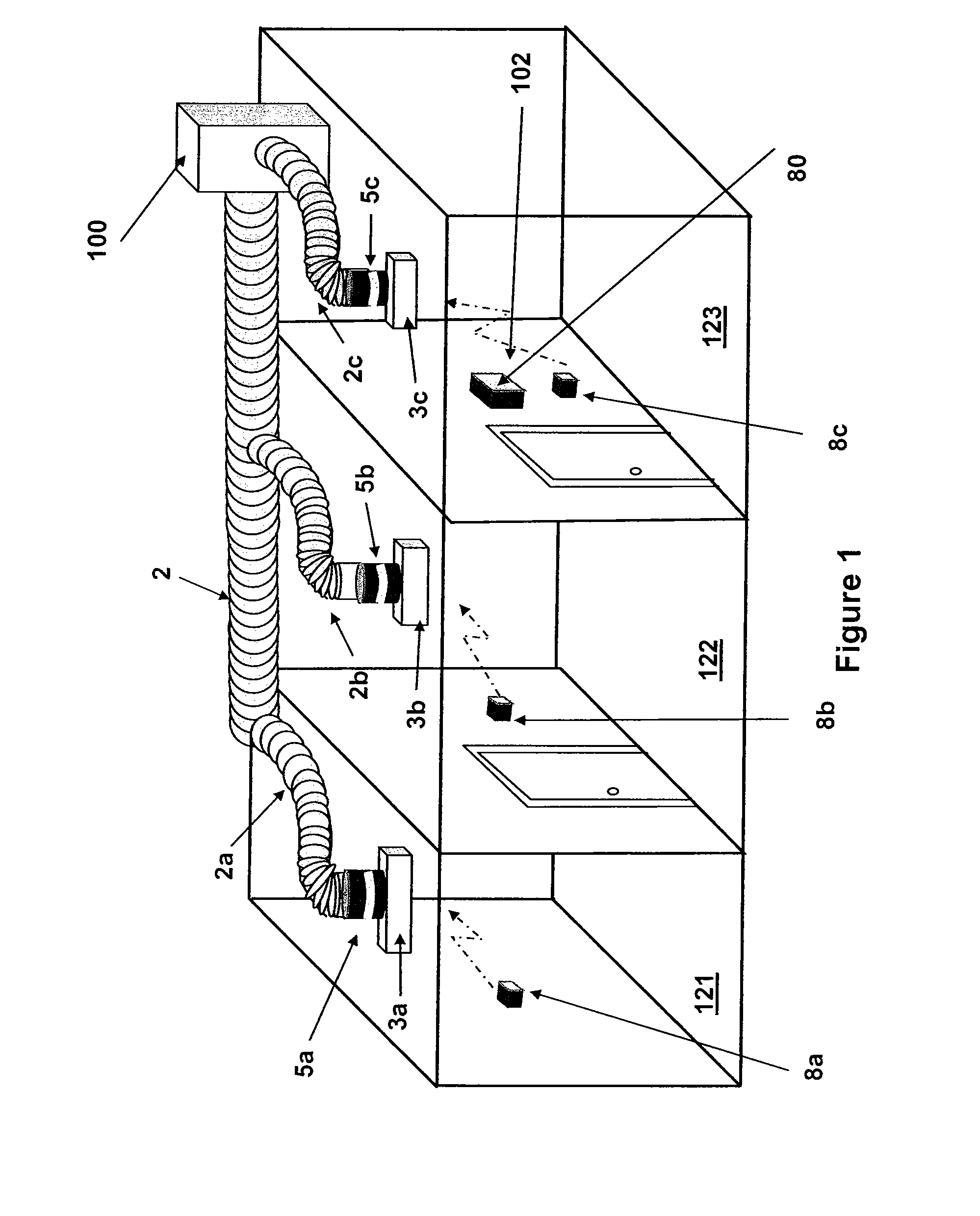
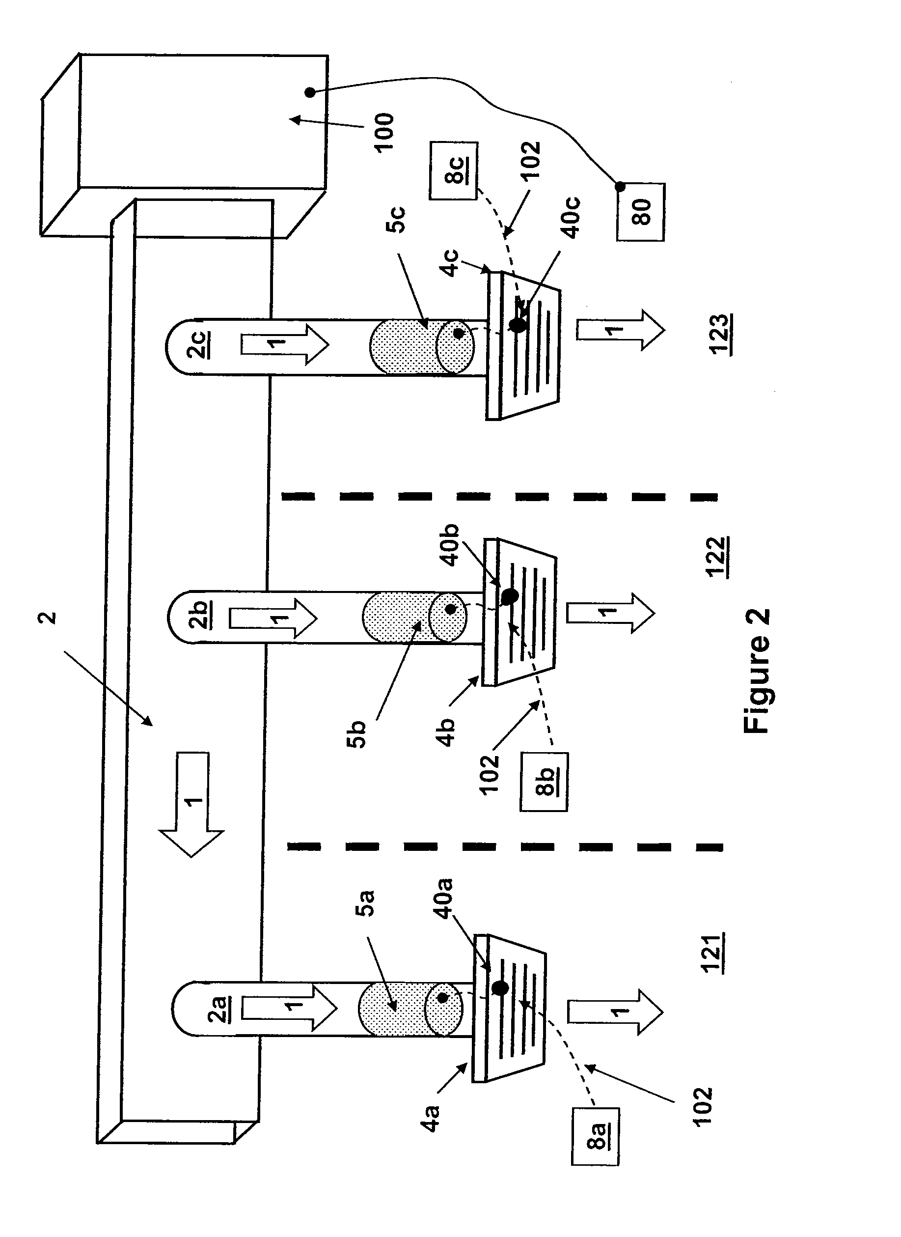
[0044]FIG. 1 illustrates an environmental control system 2...


PUM


Abstract

The present invention is generally directed to an apparatus and a method for controlling an environment in a location. In one aspect, an apparatus for controlling an environmental condition in a location is provided. The apparatus includes a flow control device, wherein the flow control device is connectable to an environmental control unit via a conduit. The flow control device comprising a flow restriction member configured to selectively control an airflow into the location and a controller member configured to autonomously actuate the flow restriction member based upon the environmental condition in the location. In another aspect, a method for controlling an environmental condition in a first location and a second location is provided. In a further aspect, a system for controlling an environmental condition in a first location and a second location is provided. In yet a further aspect, a method for controlling an environmental condition in a location is provided.

Description

CROSS-REFERENCE TO RELATED APPLICATIONS [0001] This application is a continuation-in-part of co-pending U.S. patent application Ser. No. 10 / 987,476, filed on Nov. 12, 2004, and this application also claims benefit of U.S. provisional patent application Ser. No. 60 / 750,579, filed Dec. 15, 2005. Each of the aforementioned related patent applications is herein incorporated by reference.BACKGROUND OF THE INVENTION [0002] 1. Field of the Invention [0003] Embodiments of the present invention generally relate to heating, ventilating, and air conditioning systems. More particularly, the invention relates to controlling an environmental condition in a location. [0004] 2. Description of the Related Art [0005] The typical air vents in commercial and residential settings consist of louvers which may be manually opened or closed in varying degrees. These air vents provide a limited ability to adjust the amount of airflow into a room or area, the air coming from a central environmental control un...

Claims


Application Information

Patent Timeline
Patent Type & Authority Applications(United States)
IPC IPC(8): F24F7/00F24F3/00F24F11/00
CPCF24F3/00F24F11/001F24F11/0001F24F11/30F24F2110/00F24F11/54F24F11/74
Inventor ARONSTAM, PETER S.FINCHER, ROGER W.
Owner ADAPTIVE
Why Eureka
Try Eureka