
Method to provide wireless broadband communication to a high-speed movable vehicle

a high-speed movable vehicle and wireless broadband technology, applied in vehicle position/course/altitude control, process and machine control, instruments, etc., can solve the problems of high number of wlan hot spots, inability to communicate via wimax, and fast moving vehicles, etc., and achieve the effect of installation costs

Active Publication Date: 2007-08-02
GOOGLE LLC
View PDF1 Cites 15 Cited by
  • Summary
  • Abstract
  • Description
  • Claims
  • Application Information

AI Technical Summary

Benefits of technology

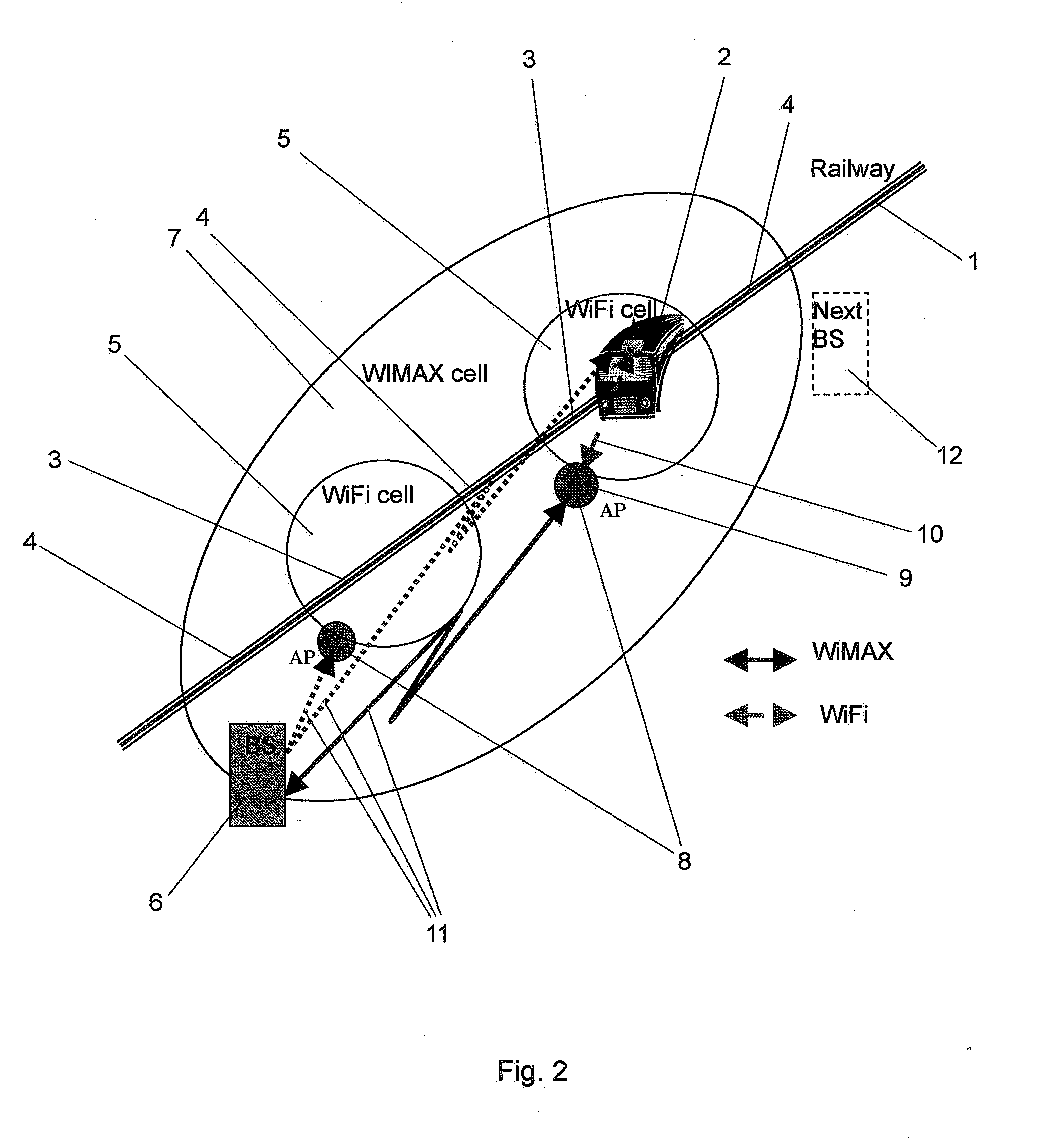
The invention provides a method for providing wireless broadband communication to high-speed movable vehicles, such as trains, by combining two technologies: WIMAX and WLAN. The method involves arranging WIMAX base stations along a route the vehicle moves along, and WLAN hot spots between the WIMAX base stations. The WIMAX base stations provide continuous coverage, while the WLAN hot spots are used for faster speeds. The WIMAX base stations act as a backhauling network for the WLAN hot spots, reducing the need for expensive fiber converters. The invention also includes means to detect the vehicle speed and decide which network to connect to based on the speed threshold. The technical effects of the invention include improved wireless communication coverage and reduced installation costs.

Problems solved by technology

The drawback of WLAN is that to provide communication to a vehicle, a very high number of WLAN hot spots are required along the route, since the theoretical outdoor range to be covered by WLAN is only about 20 km, assuming a Line of Sight (LoS), wherein the practical useable range is only about 1 to 2 km, i.e. 500 to 1000 m in each direction.
The drawback of WIMAX is that for fast moving vehicles communication via WIMAX is impossible due to Doppler shift.
Other known technologies such as solutions based on satellites do not work in tunnels.

Method used


Image

  • Method to provide wireless broadband communication to a high-speed movable vehicle
  • Method to provide wireless broadband communication to a high-speed movable vehicle
  • Method to provide wireless broadband communication to a high-speed movable vehicle

Examples


Embodiment Construction

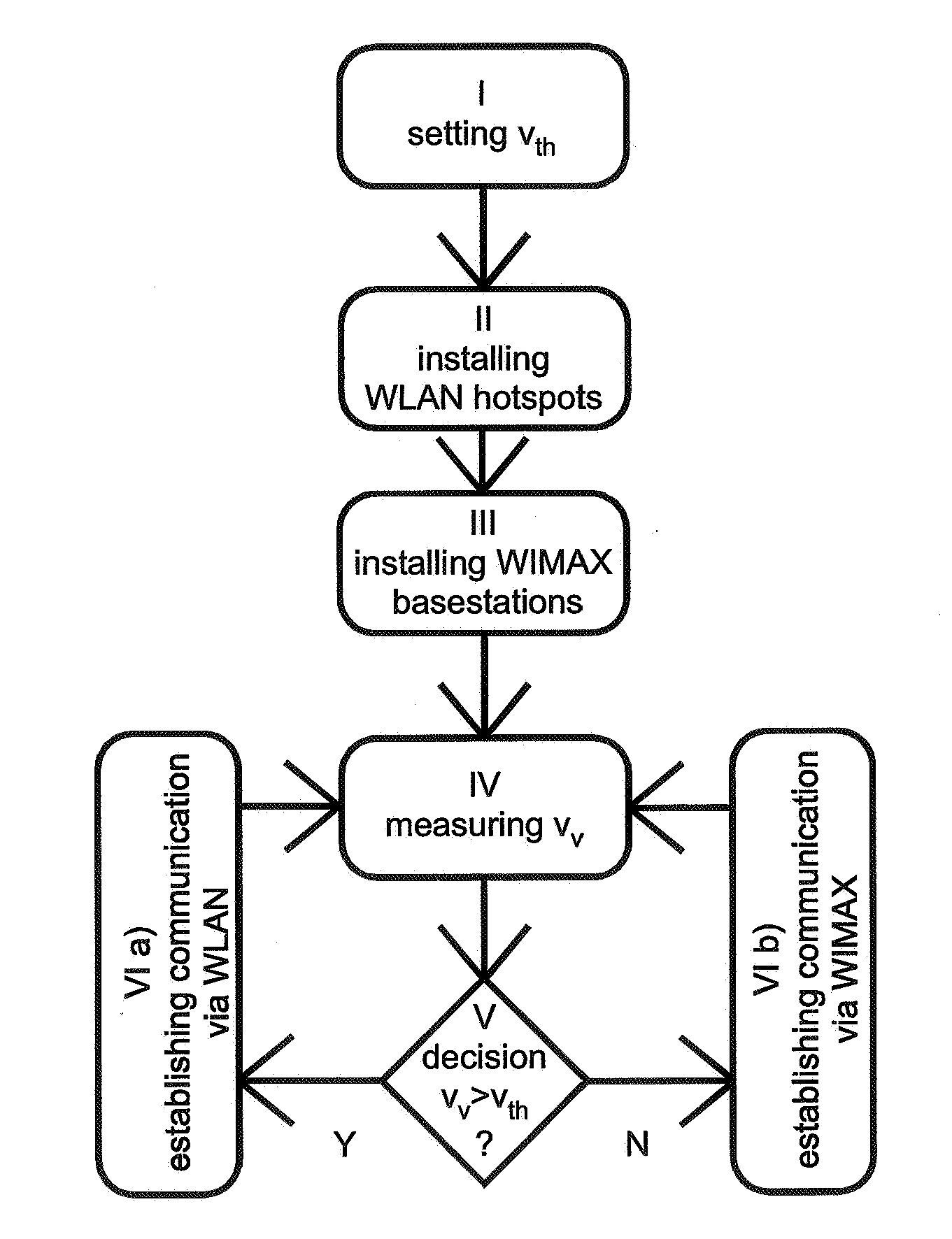
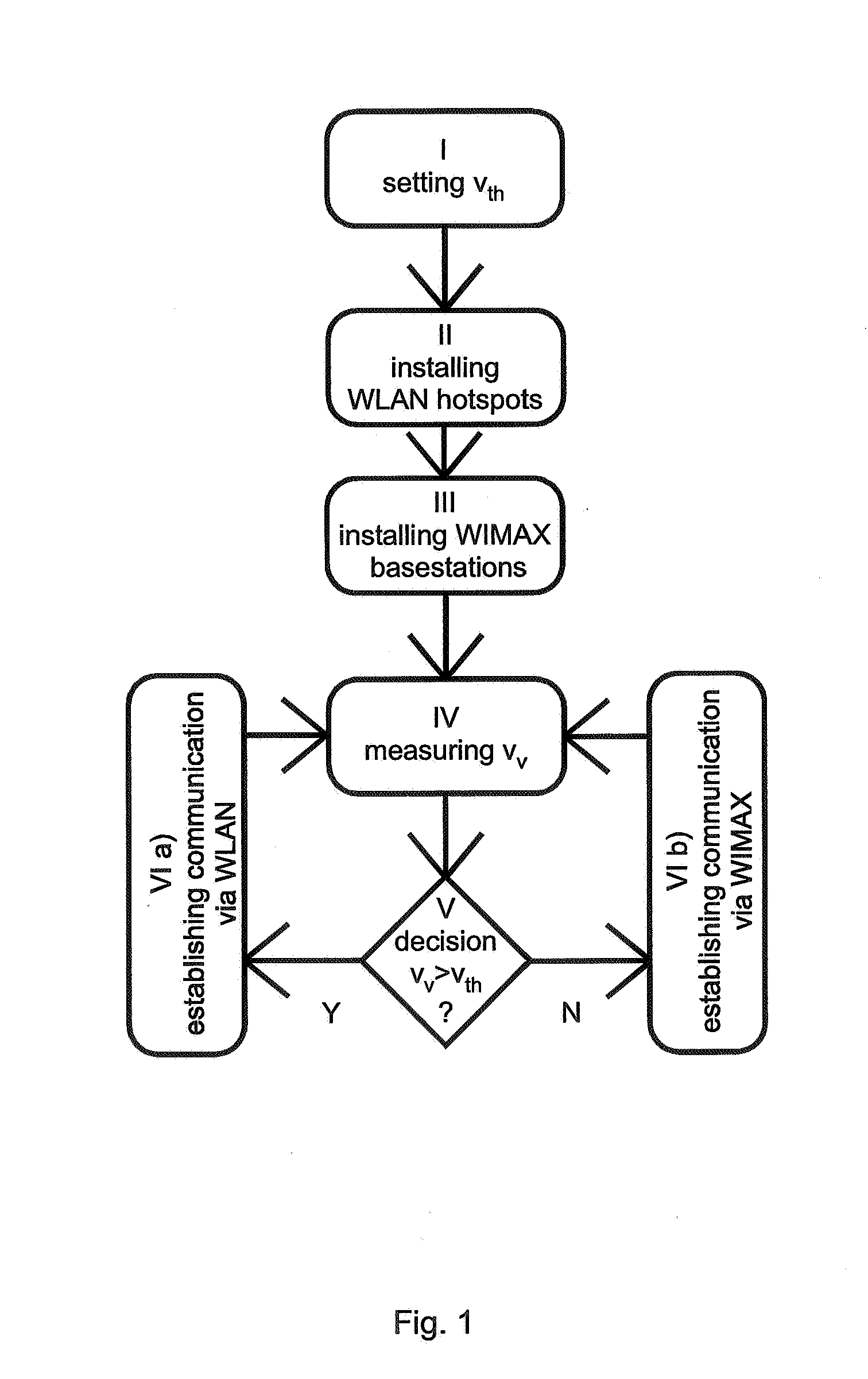
[0043]A method according to the invention is executed in the following way (FIG. 1): In a first step I, a speed threshold vth is set. The speed threshold is set below a technically given speed limitation given by the network technologies used for the wireless communication. This technically given speed limitation is due to Doppler shift, depending on vehicle speed. This threshold can change with the development of wireless network technologies.

[0044]In a second step II WLAN hot spots are arranged along sections of a route having no or a higher speed limit than the predefined speed threshold. On such a section, a vehicle can move faster than the speed threshold mentioned above.

[0045]In a third step III WIMAX base stations are arranged along sections of a route having a speed limit lower than the predefined speed threshold. On such a section, a vehicle is not allowed to move faster than the speed threshold mentioned above.

[0046]In a fourth step IV, the actual vehicle speed vv is measu...


PUM


Abstract

A method for providing wireless broadband communication to a high-speed movable vehicle, in particular to a high-speed train (2), is described, said method comprising the steps of:Arranging Worldwide Interoperability for Microwave Access (WIMAX) base stations (6) along a route (1) the vehicle (2) moves along,Arranging Wireless Local Area Network (WLAN) hot spots (5) along the route (1) between said WIMAX base stations (6),Upon detection of a vehicle speed (vv) above a predefined speed threshold (vth) establishing a communication (10) to said vehicle (2) using said WLAN hot spots,Upon detection of a vehicle speed (vv) below said speed threshold (vth) establishing a communication to said vehicle (2) over said WIMAX base stations (6).Furthermore a communication network to be used to execute the method mentioned above, plus a computer program product causing a computer to perform said method is described.

Description

[0001]The invention is based on a priority application EP06300096.2 which is hereby incorporated by reference.TECHNICAL FIELD[0002]The invention relates to a method for providing wireless broadband communication to a high-speed movable vehicle, in particular to a high-speed train.BACKGROUND OF THE INVENTION[0003]With increasing mobility it is important to provide communication on a high level of quality, like e.g. a high-speed Internet access, particularly to means of travel that are frequently used for business travels. Such means of travel can be e.g. trains, particularly high speed trains such as the French Train a Grande Vitesse (TGV), the German Inter City Express (ICE), the Japanese Bullet Train Shikansen and the like, magnetically levitated trains such as the Transrapid and the like, all movable with speeds up to 400 km / h and above, but also fast driving motorcars and the like. It is also thinkable to provide such communication to airplanes particularly to such airplanes flyi...

Claims


Application Information

Patent Timeline
Patent Type & Authority Applications(United States)
IPC IPC(8): G06F17/00G05D1/00H04W28/18H04W28/26H04W36/14H04W36/32H04W84/12
CPCH04W28/26H04W84/12H04W36/32H04W36/14H04W36/324H04W36/1446
Inventor SOULIE, ANTOINEFAYE, JEAN-CLAUDE
Owner GOOGLE LLC
Learn More