Device for locking-unlocking tired wheels of vehicles on a mandrel of a maintenance machine

a technology for maintenance machines and wheels, which is applied in the direction of measuring devices, expansion mandrels, instruments, etc., can solve the problems of balancing inaccuracy, affecting the operation of maintenance machines, so as to achieve high-competitive manufacturing costs

Active Publication Date: 2007-08-09
RAVAGLIOLI
View PDF5 Cites 1 Cited by
  • Summary
  • Abstract
  • Description
  • Claims
  • Application Information

AI Technical Summary

Benefits of technology

[0005] Another object of the present invention is that of providing a compact locking-unlocking device of limited size and which can be produced at highly competitive manufacturing costs.

Problems solved by technology

This is a damaging need for the functionality of the balancing machine.
Moreover, both the pressure ring nut and the springs must be driven into rotation with the mandrel, which is a source of balancing inaccuracies due to imbalances created during the rotation by the springs, which are subjected to oscillations during their rotation.
If one must work with wheels structured in a special manner, it is necessary to support them for their correct locking on the mandrel, which is tiring for the operator.

Method used


Image

  • Device for locking-unlocking tired wheels of vehicles on a mandrel of a maintenance machine
  • Device for locking-unlocking tired wheels of vehicles on a mandrel of a maintenance machine
  • Device for locking-unlocking tired wheels of vehicles on a mandrel of a maintenance machine

Examples


Embodiment Construction

[0013] In the drawings, equivalent or similar parts or components were indicated with the same reference numerals.

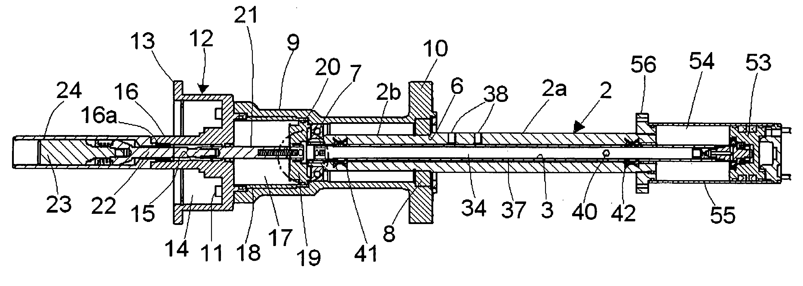
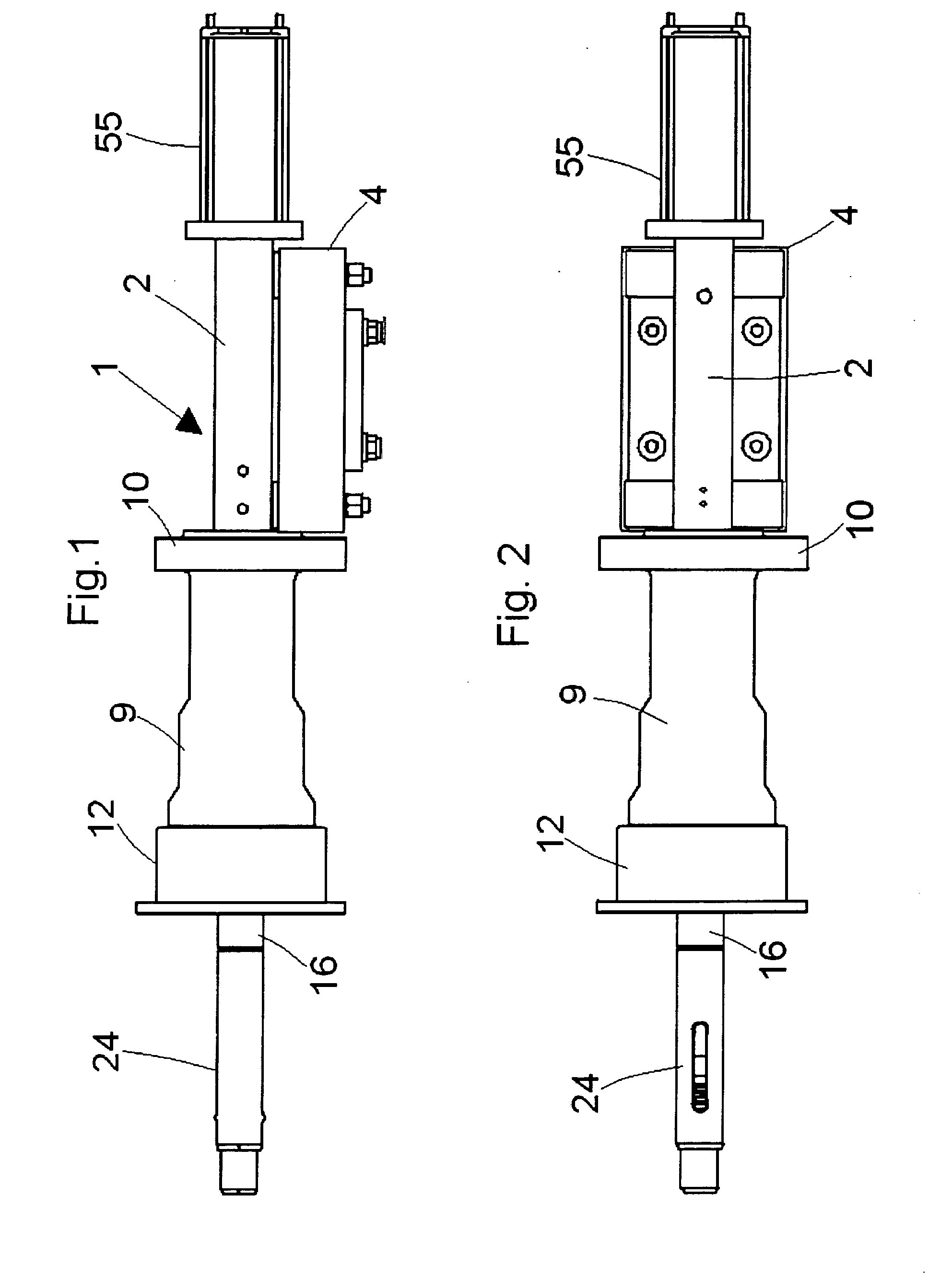
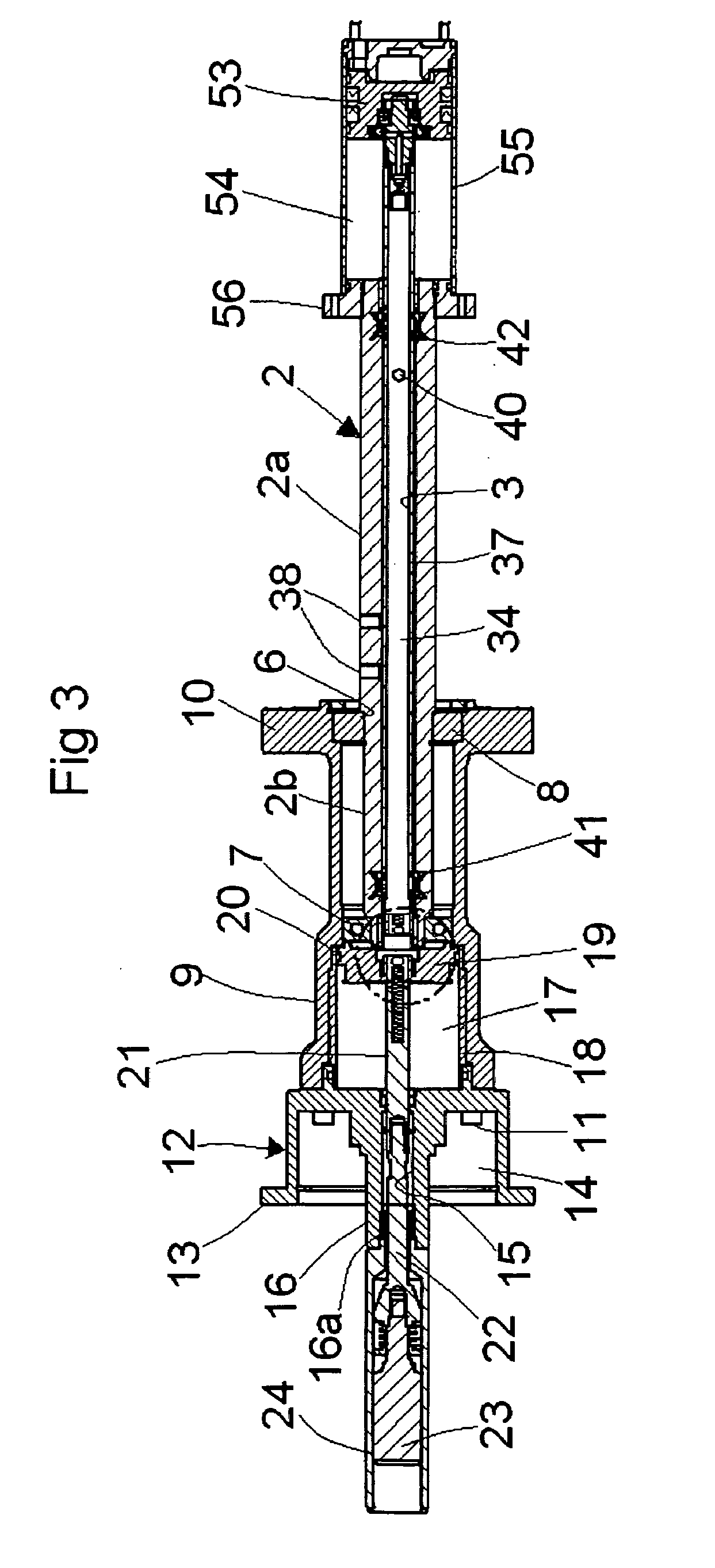
[0014] With reference first to the above-listed figures, it will be noted how a locking-unlocking device, generically indicated with 1, according to the present invention is composed of a hollow fixed support element or cylindrical shaft 2 having an inner axial cavity 3 and designed to be supported by a fixed structure 4 of a maintenance machine of tired wheels, typically a balancing machine (not shown in the drawings) of any suitable type. A tired wheel is schematically illustrated by a central section 5 of its rim in FIGS. 7 to 11.

[0015] The cylindrical shaft 2 has two outer diameters: a greater 2a and a smaller 2b, and thus in an intermediate zone thereof a peripheral shoulder 6 is delimited. At one end of the shaft 2, i.e. that with smaller outer diameter, an outer receiving seat is formed for one or more bearings 7. On the smaller external diameter portion 2b, a b...


PUM


Abstract

A locking device for a maintenance machine such as a balancing machine, of a rotating body (5), having a fixed portion comprising a hollow fixed support element (2) borne by the maintenance machine, and a control system (59), and a movable portion comprising a bell-shaped member (12) with flange (13) mounted for rotation coaxial to said hollow support element (2) and designed to support the rotating body (5), and holding or locking means (68) arranged to removably fix the rotating body (5) against said flange (13) of the bell-shaped member (12), driving means suitable for driving, upon control, said movable portion in rotation. The movable portion comprises a sleeve element (9), which is operatively connected with the driving means, mounted for rotation on said fixed support element (2) and has one of its ends extending overhanging beyond said fixed support (2) and coaxially supporting at its head the bell-shaped member (12), thereby delimiting a work chamber (17) with said bell-shaped member (12); a piston element (19) slidably mounted in the work chamber (17) and designed to control said holding means. The fixed portion comprises pressurized fluid supply means (34, 32, 48) suitable for loading, upon control of the control system (59), the work chamber (17) with pressurized fluid, and for moving away from the movable portion before the movable portion is set in rotation by the driving means, and discharge means for discharging, upon control, the work chamber (17) once the rotation of the movable part has terminated.

Description

FIELD OF INVENTION [0001] The present invention regards a device for locking-unlocking a body rotating on a rotating mandrel of an operating machine, particularly adapted for locking-unlocking tired wheels of vehicles on the rotating mandrel of a tired wheel maintenance machine, such as a balancing machine or a tire assembly-disassembly machine. BACKGROUND OF INVENTION [0002] Devices have already been proposed in the art—e. g. U.S. Pat. No. 6,763,715—including locking-unlocking devices on a rotating mandrel of balancing machines, which foresee the use of a screw pressure ring nut which is inserted on the mandrel and unscrewed and removed from it for every wheel to be balanced, as well traction springs with short work stroke. This is a damaging need for the functionality of the balancing machine. Moreover, both the pressure ring nut and the springs must be driven into rotation with the mandrel, which is a source of balancing inaccuracies due to imbalances created during the rotation ...

Claims


Application Information

Patent Timeline
Patent Type & Authority Applications(United States)
IPC IPC(8): G01M1/00
CPCG01M1/045B23B31/42
Inventor SILVANO, SANTIFAUSTO, MANGANELLI
Owner RAVAGLIOLI
Why Eureka
Try Eureka