Ultra-thin launch system for electronic devices

A technology for electronic equipment and transmission systems, applied in the direction of circuits, electrical components, electrical short antennas, etc.

Active Publication Date: 2019-08-16
IGNION SL
View PDF19 Cites 0 Cited by
  • Summary
  • Abstract
  • Description
  • Claims
  • Application Information

AI Technical Summary

Problems solved by technology

The disappearance of bulky and complex antenna elements frees up space that can be used to mount smaller and / or thinner devices, such as ultra-thin electronics, or in entirely new forms that are currently unavailable due to the presence of large antenna elements Elements

Method used


Image

  • Ultra-thin launch system for electronic devices
  • Ultra-thin launch system for electronic devices
  • Ultra-thin launch system for electronic devices

Examples


Embodiment Construction

[0102] Further features and advantages of the present invention will become apparent from the following detailed description of some preferred examples. The detailed description of some preferred examples of the invention given above is for the purpose of illustration only and by no means meant as a definition of the limits of the invention, the accompanying drawings are by reference.

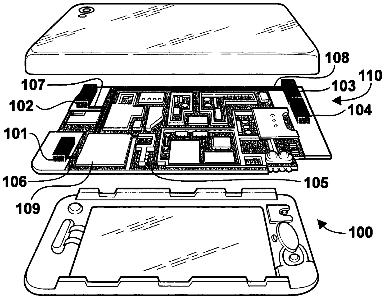
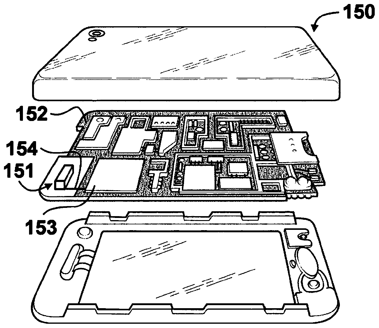
[0103] Illustrative radio devices consistent with the present invention are shown incorporating ultra-thin transmission systems such as Figure 1A and 1B shown. Figure 1A In a particular arrangement, the radio device 100 is a smart phone, but could also represent other radio devices such as a tablet or a desktop computer. The ultra-thin launch system includes a first booster rod 101, a second booster rod 102, a booster element 110, and a ground element 105 (which may comprise one or more layers of printed circuit boards). The intensifier element 110 comprises two consecutive booster rods: a...


PUM


Abstract

A wireless device includes at least one ultrathin transmitting system with an ultrathin transmitting structure and a radio frequency system. The ultra-thin launch structure includes one or more booster rods. The booster bar features an ultra-thin width and height factor for easy integration into wireless devices and can be excited in a resonant mode on the ground plane layer. This location factor allows the booster bar to achieve the best RF performance in the space available. At least one ultra-thin transmitting system is configured to transmit and receive electromagnetic wave signals in one or more frequency regions of the electromagnetic spectrum.

Description

technical field [0001] The invention mainly relates to the field of electronic equipment that needs to emit and / or receive electromagnetic wave signals, especially the ultra-thin emitting structure in wireless electronic equipment. Background technique [0002] Wireless electronic devices typically handle one or more cellular communication standards, and / or wireless connectivity standards, and / or broadcast standards. Each standard is assigned to one or more frequency bands contained within one or more regions of the electromagnetic spectrum. [0003] Therefore, a typical wireless electronic device must contain a transmission system that can operate in one or more frequency domains, with acceptable radio performance (such as: reflection coefficient, standing wave ratio, impedance bandwidth, gain, efficiency or transmission mode). The integration of the transmission system in wireless electronic equipment must effectively ensure that the overall equipment achieves good radio ...

Claims


Application Information

Patent Timeline
Patent Type & Authority Patents(China)
IPC IPC(8): H01Q1/24H01Q1/38H01Q9/04H01Q9/40H01Q21/30H01Q5/357H01Q5/50
CPCH01Q5/357H01Q5/50H01Q1/243H01Q1/38H01Q9/0485H01Q9/40H01Q21/30H01Q1/50H01Q5/335
Inventor 乔米·安古拉诺曼·托普斯奥萝拉·安杜哈尔
Owner IGNION SL
Why Eureka
Try Eureka