Torque meter

a torque meter and torque technology, applied in the field of torque meter, can solve problems such as manufacturing process difficulties, and achieve the effect of accurate torque measuremen

Inactive Publication Date: 2007-08-09
ONO SOKKI CO LTD
View PDF17 Cites 13 Cited by
  • Summary
  • Abstract
  • Description
  • Claims
  • Application Information

AI Technical Summary

Benefits of technology

[0009] The present invention relates to a torque meter that allows accurate torque measurement by detecting only torque, without being affected by the aforementioned various loads, ideally, without any influences other than torque.

Problems solved by technology

However, although Japanese Unexamined Patent Application 53-106181 can reduce the influence other than torque by virtue of the actuation structure, influences due to sensor-to-sensor unbalance, structural unbalance, etc. had to be removed to sufficiently reduce the influence, raising a problem of difficulties in the manufacturing process.

Method used


Image

  • Torque meter
  • Torque meter
  • Torque meter

Examples


exemplary embodiment 1

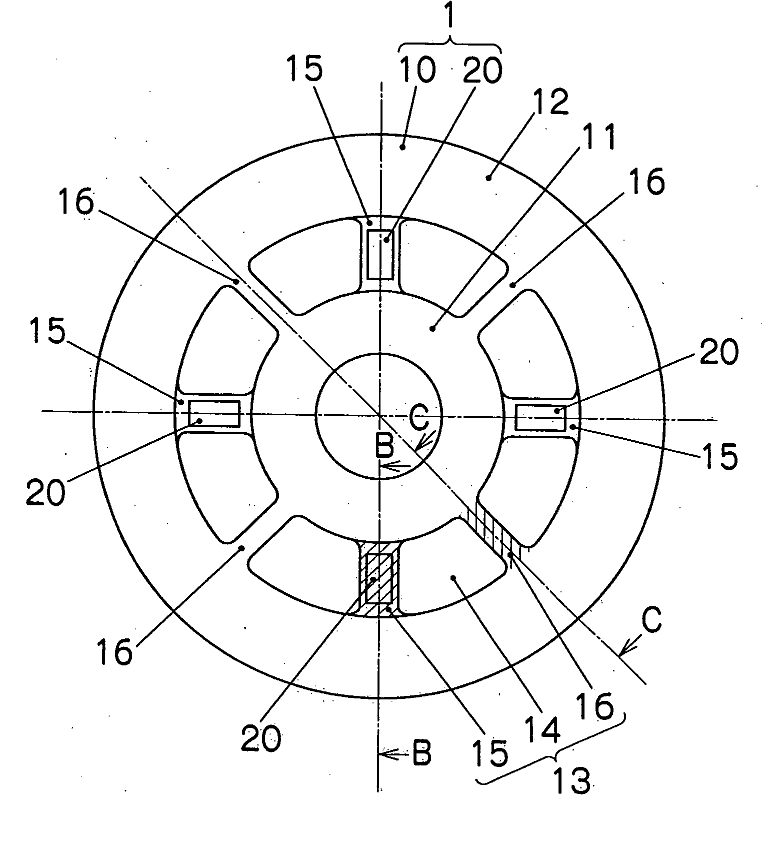
[0035]FIG. 1A to 1C are views showing embodiment 1 of the torque meter according to the present invention.

[0036] A torque meter 1 in the embodiment 1 is arranged in a power transmission channel, and includes an elastic member 10 that deforms in response to a torque to be measured and torque detection means 20 for detecting a torque based on deformation of the elastic member 10.

[0037] The elastic member 10 is arranged between a main-body part and a fixing part of a rotary drive unit (not shown). The elastic member 10 is made of a metal such as aluminum, and includes a flange-type member having a specific thickness and upper and lower surfaces arranged parallel to each other.

[0038] The elastic member 10 includes a first fixing part (input part) 11 fixed to the main-body part of the rotary drive unit, a second fixing part (output part) 12 fixed to the fixing part of the rotary drive unit, and a deforming part 13 arranged between the first and second fixing parts 11 and 12.

[0039] Th...

exemplary embodiment 2

[0060]FIG. 6 is a view showing embodiment 2 of the torque meter according to the present invention.

[0061] It is to be noted that, in the embodiments depicted below, the same numerals or the unified end numerals are given to the parts that fulfill the same function as in the embodiment 1 described above, and an overlapping description and drawings are omitted as appropriate.

[0062] With a torque meter 1B in the embodiment 2, a deforming part 13B is formed with eight grooves 14B, wherein connections between the grooves 14B include torque member 15 and load member 16 alternately.

[0063] According to the embodiment 2, even if the torque member 15 and the load member 16 are broken, the groove structures 14B will serve as a guide so that an effect of reducing danger and damage can be expected. Moreover, by changing the holes 14 in the embodiment 1 to the structure of the grooves 14B in the embodiment 2, the execution methods can also be changed, which can be selected as appropriate.

exemplary embodiment 3

[0064]FIG. 7 is a view showing embodiment 3 of the torque meter according to the present invention.

[0065] With a torque meter 1C in the embodiment 3, a deforming part 13C is formed with four grooves 14C, in which connections between the grooves 14C include two load members 16C and 16C and one torque member 15C held therebetween.

[0066] In such a manner, the number of torque members and load members may be different. Specifically, according to the embodiment 3, the number of load members can be selected in accordance with the magnitude of loads other than torque.


PUM

PropertyMeasurementUnit
torque meteraaaaaaaaaa
torqueaaaaaaaaaa
thicknessaaaaaaaaaa

Abstract

A torque meter enables highly accurate measurement of a torque by detecting only the torque, without being affected by various loads. The torque meter includes an elastic member placed in a power transmission channel and being deformed upon application with a torque being measured, and a means for detecting the torque based on the deformation of the elastic member. The torque member receives a torque being applied to the elastic member, and the load member is provided separately from the torque member, for supporting the load of the elastic member.

Description

TECHNICAL FIELD [0001] The present invention relates to torque meters for measuring a driving torque produced on an output shaft of rotary drive units such as an electric motor and a reduction gear. BACKGROUND ART [0002] A torque meter of this type serves to measure a moment for a shaft such as a rotary shaft or a stationary shaft as center. [0003] Typically, detection of torque is made by detecting a torsional force of the shaft produced by torque or a torsional angle of the shaft changed by torque. As a means for detecting the torsional force, means is known which uses a piezoelectric element for generating an electric charge proportional to the force received. Moreover, a magnetostrictive element, which is an element using a material having magnetic characteristics that change when subject to a force, serves to detect torque as force. On the other hand, as a means for detecting torsional angle, a distortion-gage system and a rotation pulse phase difference system are well known. ...

Claims


Application Information

Patent Timeline
Patent Type & Authority Applications(United States)
IPC IPC(8): G01L3/00G01L3/10G01L3/14
CPCG01L3/1457
Inventor TAKAMURA, AKIOOTSUKA, KENICHIMIYATA, TOORU
Owner ONO SOKKI CO LTD
Why Eureka
Try Eureka