Deployable Contour Crafting

Inactive Publication Date: 2007-08-09
UNIV OF SOUTHERN CALIFORNIA
View PDF35 Cites 79 Cited by
  • Summary
  • Abstract
  • Description
  • Claims
  • Application Information

AI Technical Summary

Benefits of technology

[0019] The positioning system may include one o

Problems solved by technology

Quickly and easily deploying this technology at

Method used


Image

  • Deployable Contour Crafting
  • Deployable Contour Crafting
  • Deployable Contour Crafting

Examples


Embodiment Construction

[0052] Illustrative embodiments of certain concepts are now discussed. This discussion illustrates these concepts; it does not set forth all of their embodiments. Numerous other embodiments may be used in addition or instead. Details that are apparent are also often omitted to save space or for more effective presentation.

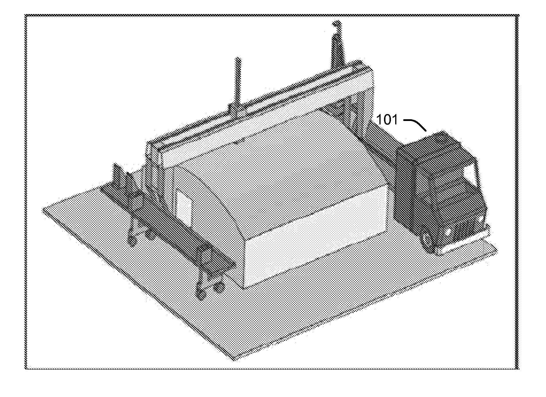
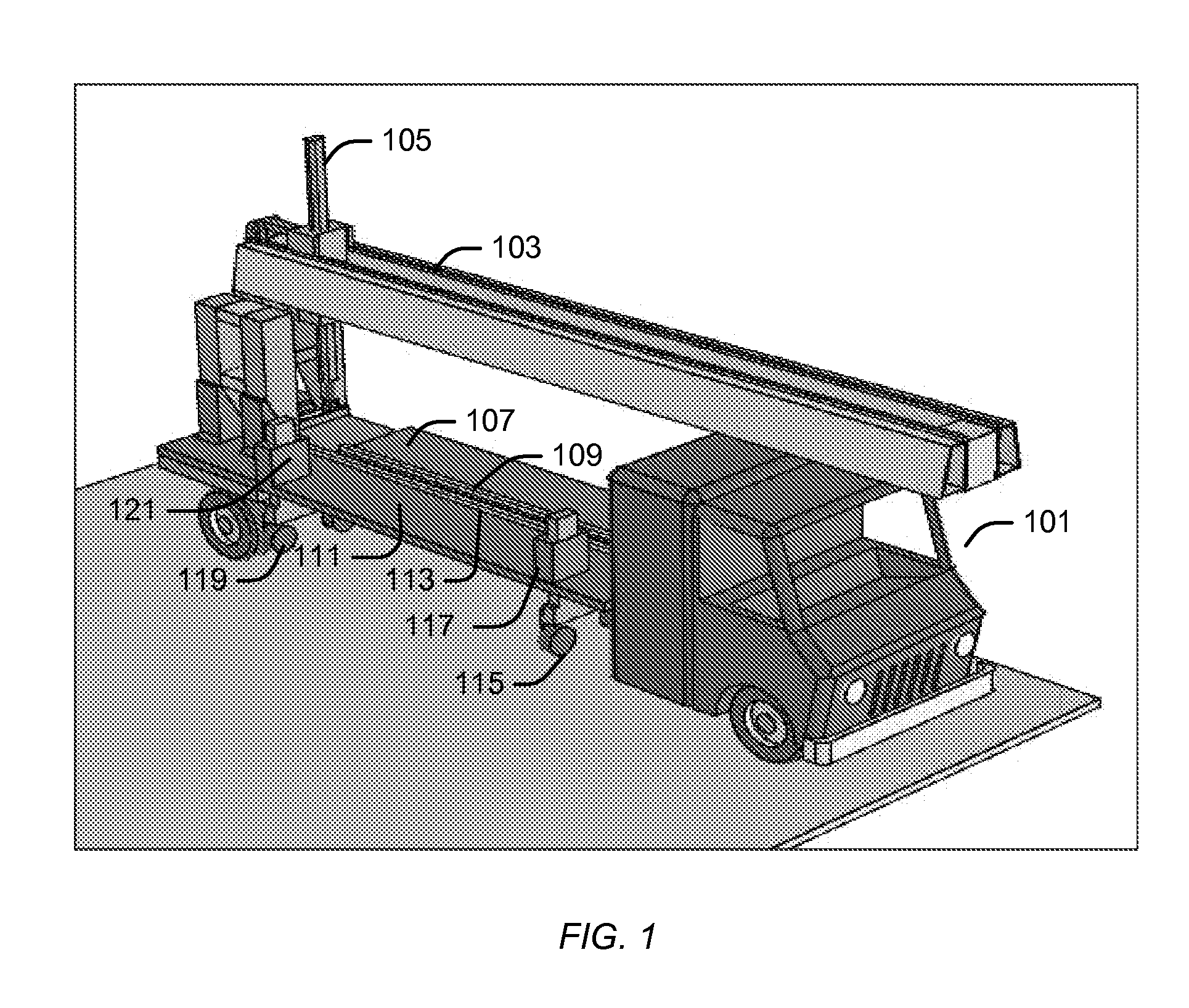
[0053]FIG. 1 illustrates a deployable crafting machine having a gantry system in a collapsed and inoperable state.

[0054] As illustrated in FIG. 1, a vehicle 101 may have a bridge 103 stored on it, a material delivery nozzle 105 movably attached to the bridge 103, a vehicle platform 107 with a vehicle rail 109 attached to it, and a mobile platform 111 with a mobile rail 113 attached to it. The vehicle platform 107 may be pivotally attached to the vehicle 101 with a vertical pivot, thus allowing the vehicle platform 107 to be rotated in a horizontal plane. The vehicle platform 107 may instead be fixedly attached to the vehicle 101. The vehicle platform 107 may inst...


PUM


Abstract

A deployable crafting machine may include a vehicle and a gantry system. The gantry system may be configured to be collapsed on the vehicle during which the gantry system is inoperable and to be expanded during which the gantry system is operable and supported at least in part by the vehicle. A deployable crafting process may include moving a vehicle to a first location while a gantry system is stored on the vehicle in a collapsed and inoperable state and expanding the gantry system into an operable state after the vehicle arrives at the first location during which the gantry system is supported at least in part by the vehicle.

Description

CROSS-REFERENCE TO RELATED APPLICATIONS [0001] This application is based upon and claims priority to U.S. Provisional Patent Application Ser. No. 60 / 730,418, entitled “Deployable Contour Crafting Machine,” Attorney Docket No. 28080-191, filed Oct. 26, 2006. This application is also related to U.S. patent application Ser. No. 10 / 760,963, entitled “Multi-Nozzle Assembly for Extrusion of Wall,” Attorney Docket No. 28080-115, filed Jan. 20, 2004, which claims priority to and incorporates by reference U.S. Provisional Application Ser. No. 60 / 441,572, entitled “Automated Construction,” Attorney Docket No. 28080-097, filed Jan. 21, 2003. This application is also related to U.S. patent application Ser. No. 11 / 040,401, entitled “Robotic Systems for Automated Construction,” Attorney Docket No. 28080-149, filed Jan. 21, 2005, U.S. patent application Ser. No. 11 / 040,602, entitled “Automated Plumbing, Wiring, and Reinforcement,” Attorney Docket No. 28080-154, filed Jan. 21, 2005, and U.S. patent...

Claims


Application Information

Patent Timeline
IPC IPC(8): B66C23/36
CPCB66C5/00E04G21/04B66C23/36Y10T137/6855Y10T137/8807
Inventor KHOSHNEVIS, BEHROKH
Owner UNIV OF SOUTHERN CALIFORNIA
Why Eureka
Try Eureka