Supply Tray And Image Forming Apparatus For Use Therewith

a technology of image forming apparatus and supply tray, which is applied in the direction of thin material processing, article separation, printing, etc., can solve the problems of insufficient reliable recording medium storing portion, feeding failure, and guide plate sliding away spontaneously from the optimal position

Active Publication Date: 2007-08-09
BROTHER KOGYO KK
View PDF12 Cites 12 Cited by
  • Summary
  • Abstract
  • Description
  • Claims
  • Application Information

AI Technical Summary

Benefits of technology

[0009]In an embodiment of this invention, a supply tray is provided which comprises a guide plate that is slidably disposed in an upper portion of the supply tray and that is configured to reliably feed a recording medium, which is different in size or type, or both, from that loaded on the supply tray. The supply tray for use in an image forming apparatus may comprise a first tray configured to receive a stack of first recording mediums thereon, a second tray disposed in an upper portion of the first tray, such that the second tray is slidable in a predetermined direction, the second tray configured to receive at least one, second recording medium thereon, wherein the first recording medium is a different size, or type, or both, from the second recording medium; and a locking mechanism configured to secure the second tray at a predetermined position with respect to the first tray.

Problems solved by technology

Even if the user slides the guide plate to the optimum position, the guide plate may slide away spontaneously from the optimum position due to an external force, such as vibration and impact.
If the guide plate does not reach or remain at the optimum position, the supply roller does not feed or take up the recording medium, resulting in a feeding failure.
Thus, a reliable recording medium storing portion is not provided.

Method used


Image

  • Supply Tray And Image Forming Apparatus For Use Therewith
  • Supply Tray And Image Forming Apparatus For Use Therewith
  • Supply Tray And Image Forming Apparatus For Use Therewith

Examples


first embodiment

[0036]the invention is described in detail with reference to the accompanying drawings.

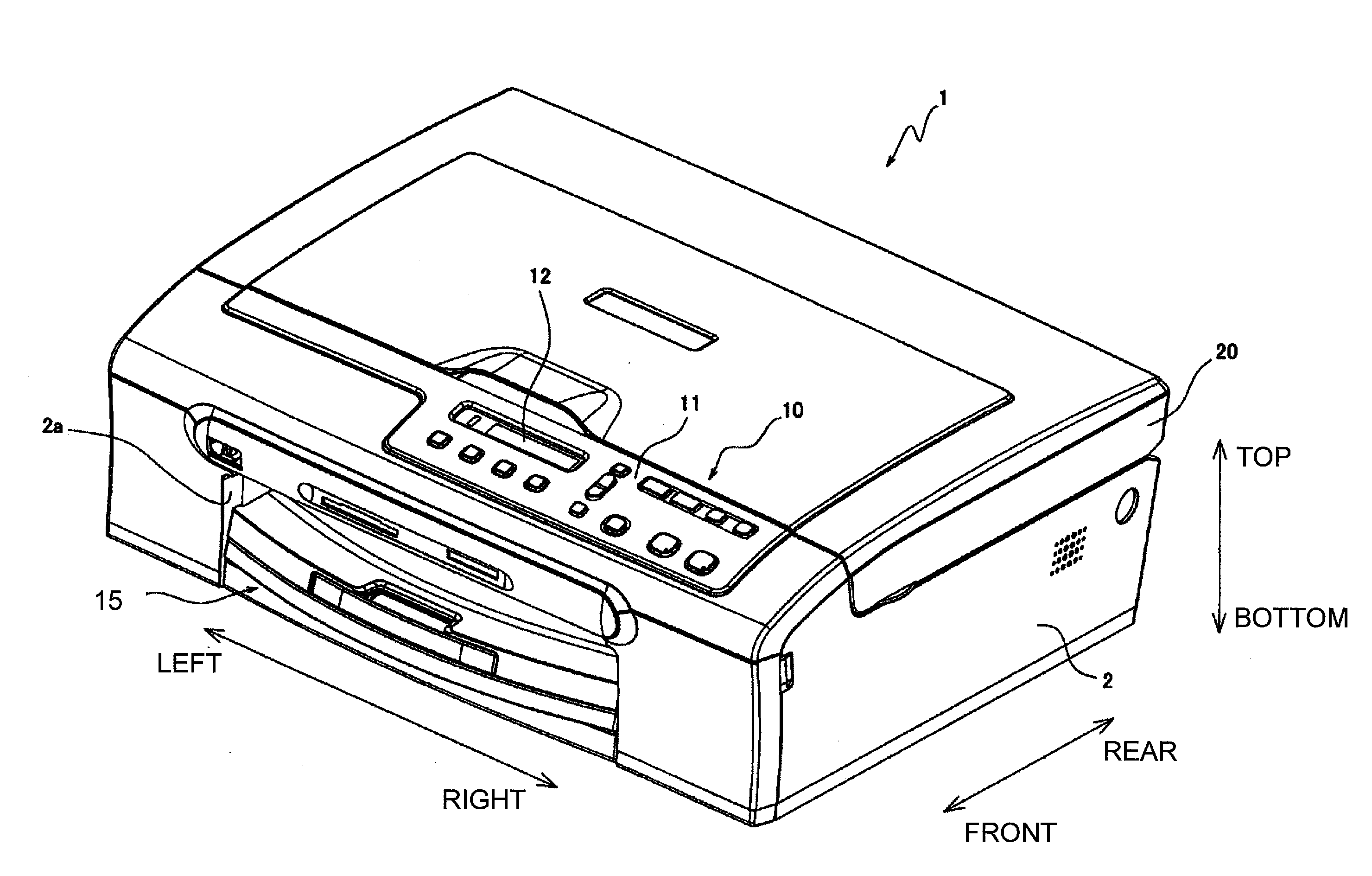
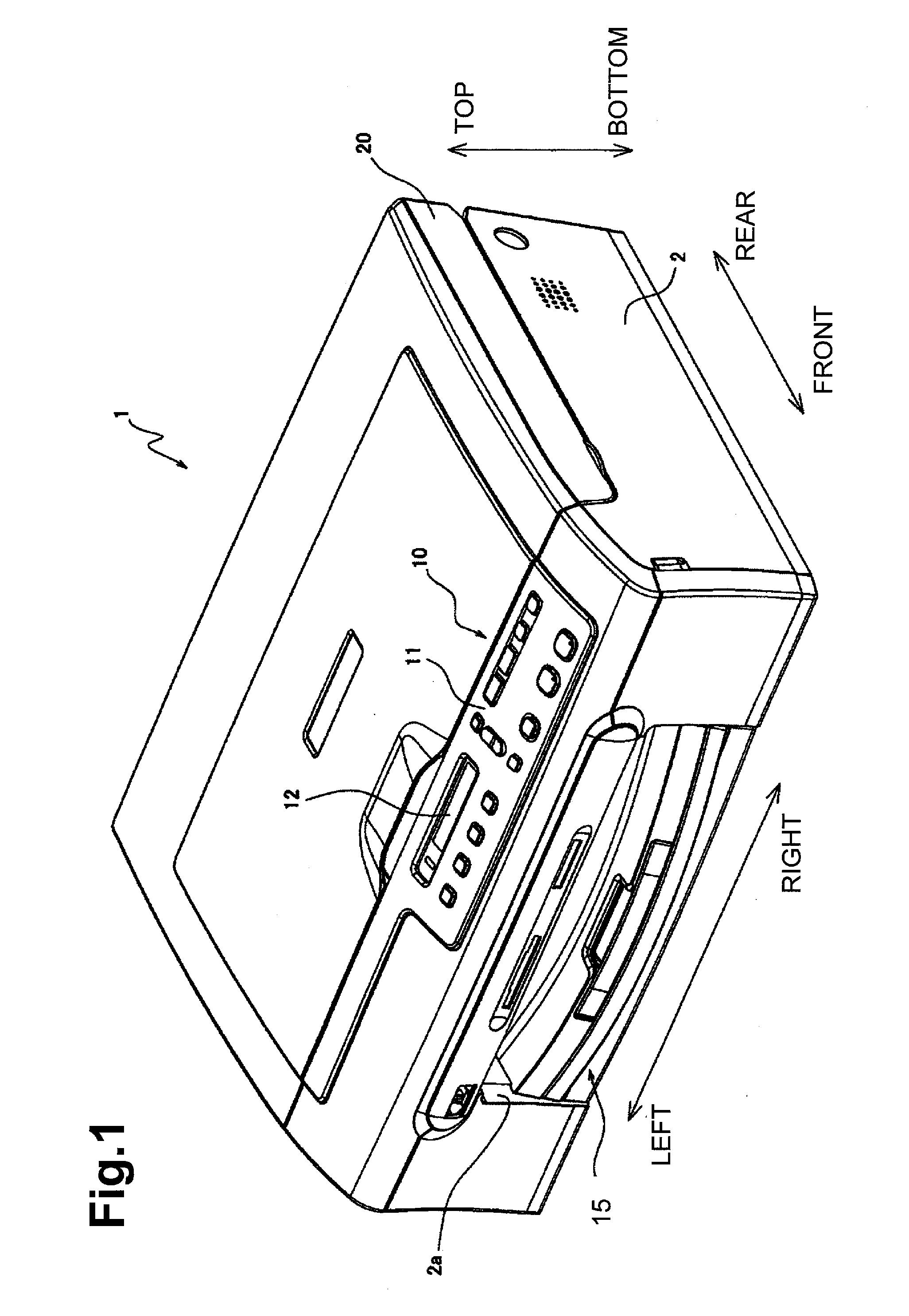
[0037]In the following description, the top and bottom sides of an image forming apparatus 1 are indicated with reference to FIG. 1 in which image forming apparatus 1 is in usual service conditions. The side of image forming apparatus 1, on which an operation panel 10 is provided, is referred to as the front, and the side substantially opposite to the side on which operation panel 10 is provided is referred to as the rear. The right and left sides of image forming apparatus 1 are defined when image forming apparatus 1 is viewed from the front side.

[0038]A general structure of image forming apparatus 1 now is described. Image forming apparatus 1 is a multi-function apparatus having a printer function, a scanner function, a color copy function, and a facsimile function. As shown in FIG. 1, the appearance of image forming apparatus 1 is formed by a body casing 2 which may be made of resin and shaped ...

second embodiment

[0072]the invention is described with reference to FIGS. 9-12.

[0073]In the second embodiment, instead of second tray 40 described in the first embodiment, a second tray 100 (FIGS. 11 and 12) is mounted on main tray 30. Second tray 100 comprises a sliding portion 100a and a pivotable portion 100b. In the second embodiment, elements, except for the second tray 100, are similar to or identical with those described in the first embodiment, and are designated by similar numerals. Thus, the descriptions of those similar or identical elements are omitted here for the sake of brevity.

[0074]As shown in FIG. 9, sliding portion 100a includes a locking member 110. Locking member 110 and two openings 83, 84, which are provided on sidewall 35 of main tray 30, comprise a locking mechanism. Sliding portion 100a has a substantially similar structure to that of sliding portion 40a of the first embodiment, and is slidably engaged with main tray 30. A point of difference between sliding portions 100a a...

third embodiment

[0092]the invention now is described with reference to FIGS. 13-16.

[0093]In the third embodiment, instead of second tray 40 described in the first embodiment, a second tray 150 (FIG. 13) is mounted on main tray 30. Second tray 150 comprises a sliding portion 150a and a pivotable portion 150b. In the third embodiment, elements, except for second tray 150, are similar or identical to those described in the first embodiment, and are designated by similar numerals. Thus, the descriptions of such similar or identical elements are omitted here for the sake of brevity.

[0094]As shown in FIG. 13, sliding portion 150a includes two locking members 160. Each sidewall 35 of main tray 30 is provided with openings 83 and 84. Locking members 160 and openings 83, 84 comprise a locking mechanism. Sliding portion 150a has a substantially similar structure to that of sliding portion 40a of the first embodiment, and slidably engages with main tray 30. Nevertheless, a point of difference between sliding ...


PUM

PropertyMeasurementUnit
sizeaaaaaaaaaa
shapeaaaaaaaaaa
widthaaaaaaaaaa

Abstract

A supply tray includes a first tray configured to receive a stack of recording medium thereon, and a second tray configured to receive at least one recording medium thereon, which is different in size or type, or both, from the stack of recording medium received on the first tray. The second tray is disposed in an upper portion of the first tray and is slidable within a predetermined direction. The supply tray further includes a locking mechanism configured to place and to fix the second tray in position with respect to the first tray.

Description

CROSS REFERENCE TO RELATED APPLICATION[0001]This application claims priority from Japanese Patent Application Nos. 2006-027292, filed Feb. 3, 2006, and 2006-350254, filed Dec. 26, 2006, the entire subject matters of which are incorporated herein by reference.BACKGROUND OF THE INVENTION[0002]1. Field of the Invention[0003]The invention relates to a supply tray configured to receive and store a stack of recording mediums and to supply the recording mediums one-by-one to an image forming apparatus and, more particularly, to a supply tray having a plurality of tiers arranged one above the next, and an image forming apparatus for use therewith.[0004]2. Description of Related Art[0005]A known image forming apparatus, such as a printer, includes a recording medium storing portion for receiving and storing recording mediums, such as sheets of paper therein. The image forming apparatus is configured to feed a recording medium stored in the recording medium storing portion to a location at wh...

Claims


Application Information

Patent Timeline
Patent Type & Authority Applications(United States)
IPC IPC(8): B41J2/01
CPCB41J13/103B65H1/26B65H2301/423245B65H2405/332B65H2405/121B65H2405/31B65H2402/515B65H2405/115B65H1/266B65H2402/51
Inventor ASADA, TETSUOSHIOHARA, YUKIOWAKAKUSA, KEISUKE
Owner BROTHER KOGYO KK
Why Eureka
Try Eureka