Method and apparatus for feeding joining elements

a technology of joining elements and feeding methods, applied in the direction of pile separation, manufacturing tools, transportation and packaging, etc., can solve the problems of time-consuming and laborious undocking process, and achieve the effect of convenient magazine filling and faster completion

Inactive Publication Date: 2013-03-21
NEWFREY
View PDF27 Cites 12 Cited by
  • Summary
  • Abstract
  • Description
  • Claims
  • Application Information

AI Technical Summary

Benefits of technology

[0012]According to an aspect of the invention, the filling station has a permanently continuous tubular section. The filling station thus does not need to have an outlet closure, via which the escape of joining elements out of the filling station is blocked. Such a filling station may be less mechanically complex.
[0013]According to an aspect of the invention, there is no inlet closure on the magazine. This facilitates the filling of the magazine in the filling station. In order to avoid joining elements exiting the filling station in an unimpeded manner, an inquiry may be made as to whether an inlet opening of the magazine is aligned with the outlet opening of the filling station. The inquiry may take

Problems solved by technology

Furthermore, docking and undocking is a relatively time-consuming process.
Furthermore, the tubular sectio

Method used


Image

  • Method and apparatus for feeding joining elements
  • Method and apparatus for feeding joining elements
  • Method and apparatus for feeding joining elements

Examples


Embodiment Construction

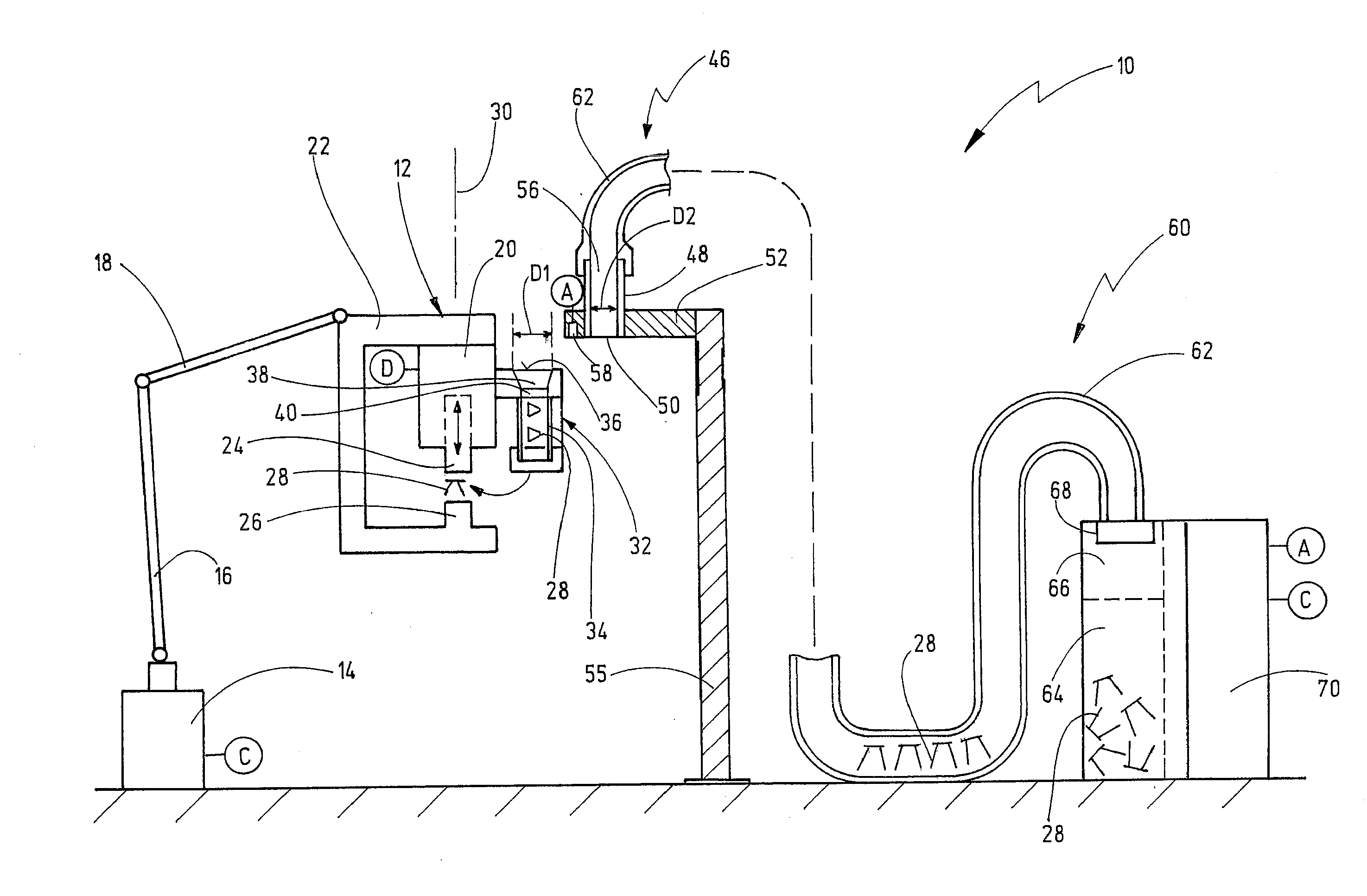
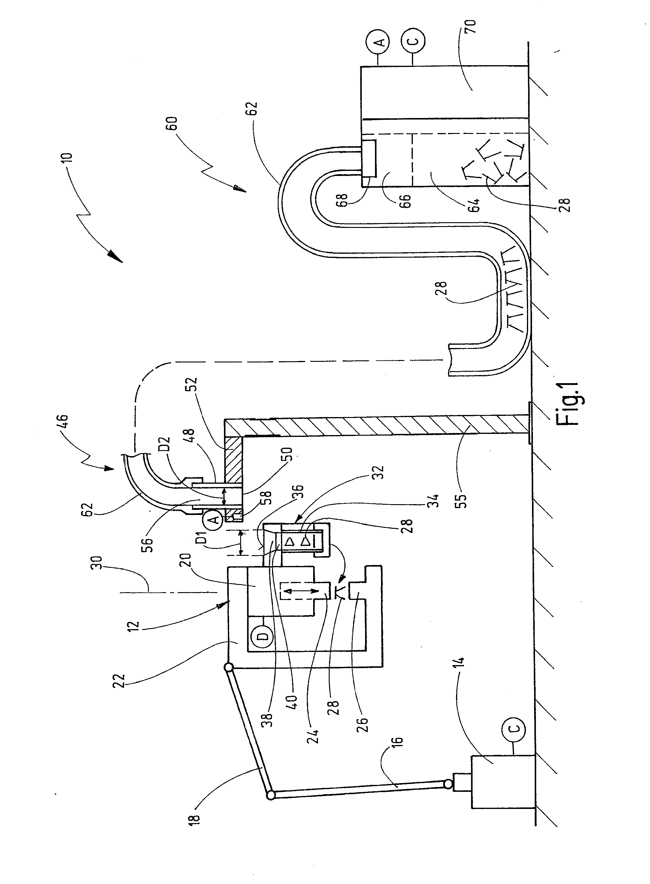
[0040]Referring now more particularly to the drawings, FIG. 1 illustrates one embodiment of a joining assembly 10 for producing joined connections by means of joining elements. In the present case, the joining assembly 10 is configured, in particular, for punch riveting. In a corresponding way, however, the joining assembly 10 can also be configured, for example, for producing stud joined connections (stud welding, stud adhesion, etc.).

[0041]The joining assembly 10 has a joining head 12 which is connected to a programmable handling unit in the form of a robot 14. In more precise terms, the robot 14 has, for example, a first arm 16 and a second arm 18, the joining head 12 being fixed on the second arm 18.

[0042]A joining tool 20 in the form of a punch riveting tool is fixed on the joining head 12. The joining tool 20 contains a C-frame 22. A ram 24 of the joining tool 20, which ram 24 can be moved in a joining direction, is mounted at an upper end of the C-frame 22. A die 26 is fixed ...


PUM

PropertyMeasurementUnit
Diameteraaaaaaaaaa
Shapeaaaaaaaaaa

Abstract

A method and apparatus for feeding joining elements to a joining tool is presented. The joining tool may be movable by a programmable handling unit, and a magazine for receiving at least one joining element may be mounted on the joining tool. The magazine may be moved to a filling station that has a tubular section with an outlet opening. An inlet opening of the magazine may be oriented in relation to the outlet opening. At least one joining element may be conveyed to the tubular section so that it passes through the tubular section, the outlet opening, the inlet opening, and into the magazine. During the orienting, the magazine may be oriented in relation to the outlet opening such that the magazine is spaced apart from the filling station during the conveying of the at least one joining element.

Description

CROSS-REFERENCE TO RELATED APPLICATIONS[0001]This application claims the benefit under 35 U.S.C. §119(a)-(d) to German Patent Application No. 102011113832.7, entitled “Method and Apparatus for Feeding Joining Elements,” filed Sep. 21, 2011, the contents of which are hereby incorporated by reference in their entirety.BACKGROUND[0002]1. Field[0003]The present invention generally relates to a method and apparatus for feeding joining elements to a joining tool.[0004]2. Description of Related Art[0005]It is known in the field of joining technology to perform joining connections using joining elements. These methods comprise, for example, the joining of joining elements onto workpieces, the joining elements being used in this case frequently as anchors for further fastening means. Joining methods of this type are known in the form of stud welding, stud adhesion or thermoplastic stud joining. Here, the studs can be rotationally symmetrical joining elements, but can also be irregularly shap...

Claims


Application Information

Patent Timeline
IPC IPC(8): B65H1/00
CPCB23P19/005B21J15/32
Inventor SCHUG, ALEXANDERSTEINMULLER, FLORIANSPIESS, MANUELDIETZ, SIMON
Owner NEWFREY
Why Eureka
Try Eureka