Recording medium feeder with multiple frictional surfaces and image recording device

a technology of frictional surface and feeder, which is applied in the direction of transportation and packaging, thin material processing, article separation, etc., can solve the problems of motor burnout, low friction coefficient, and difficulty in sliding in relation of the processing face of the lowermost sheet of paper, etc., to achieve high friction coefficient, simple configuration, and high friction coefficient

Inactive Publication Date: 2008-11-25
BROTHER KOGYO KK
View PDF21 Cites 10 Cited by
  • Summary
  • Abstract
  • Description
  • Claims
  • Application Information

AI Technical Summary

Benefits of technology

[0011]According to a first aspect of the invention, there is provided a recording medium feeder including: a tray on which a plurality of recording medium are to be stacked; a feed roller that feeds the recording medium stacked on the tray; a first friction member provided on the tray and having high friction coefficient; and a second friction member provided on the tray at a position opposing the feed roller and having low friction coefficient that is lower than the friction coefficient of the first friction member, wherein the first friction member is configurable to be in one of positions of a protruded position in which a surface of the first friction member is protruded from a surface of the second friction member towards the feed roller and a retracted position in which the surface of the first friction member is arranged to be not higher than the surface of the second friction member.
[0011]According to a first aspect of the invention, there is provided a recording medium feeder including: a tray on which a plurality of recording medium are to be stacked; a feed roller that feeds the recording medium stacked on the tray; a first friction member provided on the tray and having high friction coefficient; and a second friction member provided on the tray at a position opposing the feed roller and having low friction coefficient that is lower than the friction coefficient of the first friction member, wherein the first friction member is configurable to be in one of positions of a protruded position in which a surface of the first friction member is protruded from a surface of the second friction member towards the feed roller and a retracted position in which the surface of the first friction member is arranged to be not higher than the surface of the second friction member.
[0010]The present invention has been conceived to solve the problems, and one of objects thereof is to provide a recording medium feeder that feeds a last sheet of paper without fail even when the sheet (recording medium) is subjected to special surface processing, by employment of a comparatively simple configuration, and to provide an image recording device including the same.
[0012]According to a second aspect of the invention, there is provided an image recording device including: a main body case; a tray on which a plurality of recording medium are to be stacked horizontally, the tray being allowed to insert and withdraw in and from the main body case; a feed roller that feeds the recording medium stacked on the tray; a first friction member provided on the tray and having high friction coefficient; a second friction member provided on the tray at a position opposing the feed roller and having low friction coefficient that is lower than the friction coefficient of the first friction member; and an image forming section that forms image on the recording medium fed by the feed roller, wherein the first friction member is configurable to be in one of positions of a protruded position in which a surface of the first friction member is protruded from a surface of the second friction member towards the feed roller and a retracted position in which the surface of the first friction member is arranged to be not higher than the surface of the second friction member.
[0012]According to a second aspect of the invention, there is provided an image recording device including: a main body case; a tray on which a plurality of recording medium are to be stacked horizontally, the tray being allowed to insert and withdraw in and from the main body case; a feed roller that feeds the recording medium stacked on the tray; a first friction member provided on the tray and having high friction coefficient; a second friction member provided on the tray at a position opposing the feed roller and having low friction coefficient that is lower than the friction coefficient of the first friction member; and an image forming section that forms image on the recording medium fed by the feed roller, wherein the first friction member is configurable to be in one of positions of a protruded position in which a surface of the first friction member is protruded from a surface of the second friction member towards the feed roller and a retracted position in which the surface of the first friction member is arranged to be not higher than the surface of the second friction member.
[0011]According to a first aspect of the invention, there is provided a recording medium feeder including: a tray on which a plurality of recording medium are to be stacked; a feed roller that feeds the recording medium stacked on the tray; a first friction member provided on the tray and having high friction coefficient; and a second friction member provided on the tray at a position opposing the feed roller and having low friction coefficient that is lower than the friction coefficient of the first friction member, wherein the first friction member is configurable to be in one of positions of a protruded position in which a surface of the first friction member is protruded from a surface of the second friction member towards the feed roller and a retracted position in which the surface of the first friction member is arranged to be not higher than the surface of the second friction member.
[0113]According to the embodiment, a width required for arranging the first friction member and the second friction member in parallel can be reduced, thereby enabling miniaturization of the tray.
[0114]According to the embodiment, when the second friction member is constituted of a plate material of metal such as stainless steel, the second friction member has great abrasion resistance and a low friction coefficient. Accordingly, an advantage that the last sheet can be fed more reliably, as compared with a case where a synthetic resin surface is utilized as the second friction member, is exerted.
[0044]An image-reading device 12 for performing document (original) reading, and the like, for a copying function and a facsimile function is disposed above the housing 2. There is employed such a configuration that a bottom wall 11 of the image-reading device 12 is superimposed on an upper cover body 30, which will be described later, from above the same with substantially no clearance there between. The image-reading device 12 is configured such that the image-reading device 12 is vertically reclosable and rotatable on one side end of the housing 2 by way of an unillustrated pivot shaft section. Furthermore, a rear end of a document cover body 13 for covering an upper face of the image-reading device 12 is attached to a rear end of the image-reading device 12 in such a manner that the document cover body 13 can vertically pivot about a pivot shaft 12a.

Problems solved by technology

Accordingly, when the paper is stacked with the processed face (recording face) facing downward, the processed face of a lowermost sheet of paper encounters difficulty in sliding in relation to the member of high friction coefficient.
Consequently, even with a driving force of the paper feed roller, the lowermost sheet of paper cannot be separated from the member of high friction coefficient, and feeding of the last sheet is disabled.
However, when a DC (direct current) motor is employed for cost saving, a control system feeds an excessive current in an attempt to forcibly rotate the paper feed roller, whereby the motor may be burned out or a drive transmission system may be broken.

Method used


Image

  • Recording medium feeder with multiple frictional surfaces and image recording device
  • Recording medium feeder with multiple frictional surfaces and image recording device
  • Recording medium feeder with multiple frictional surfaces and image recording device

Examples


Embodiment Construction

[0038]An embodiment of the invention will be described in detail herein below.

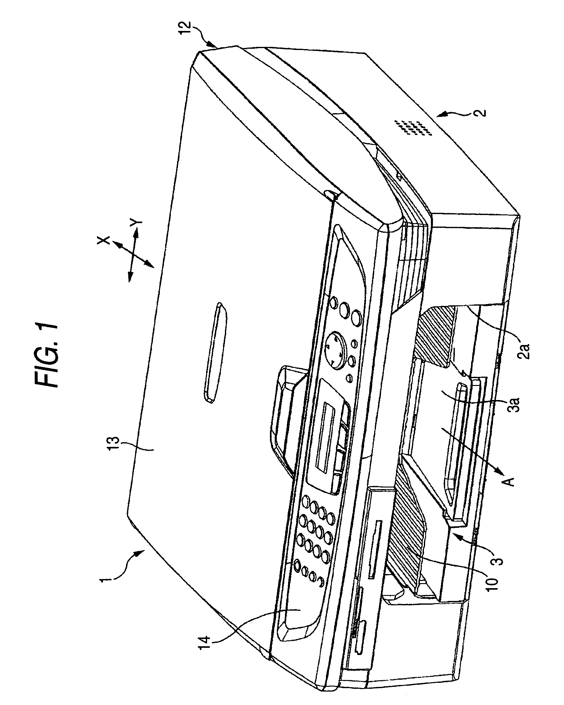
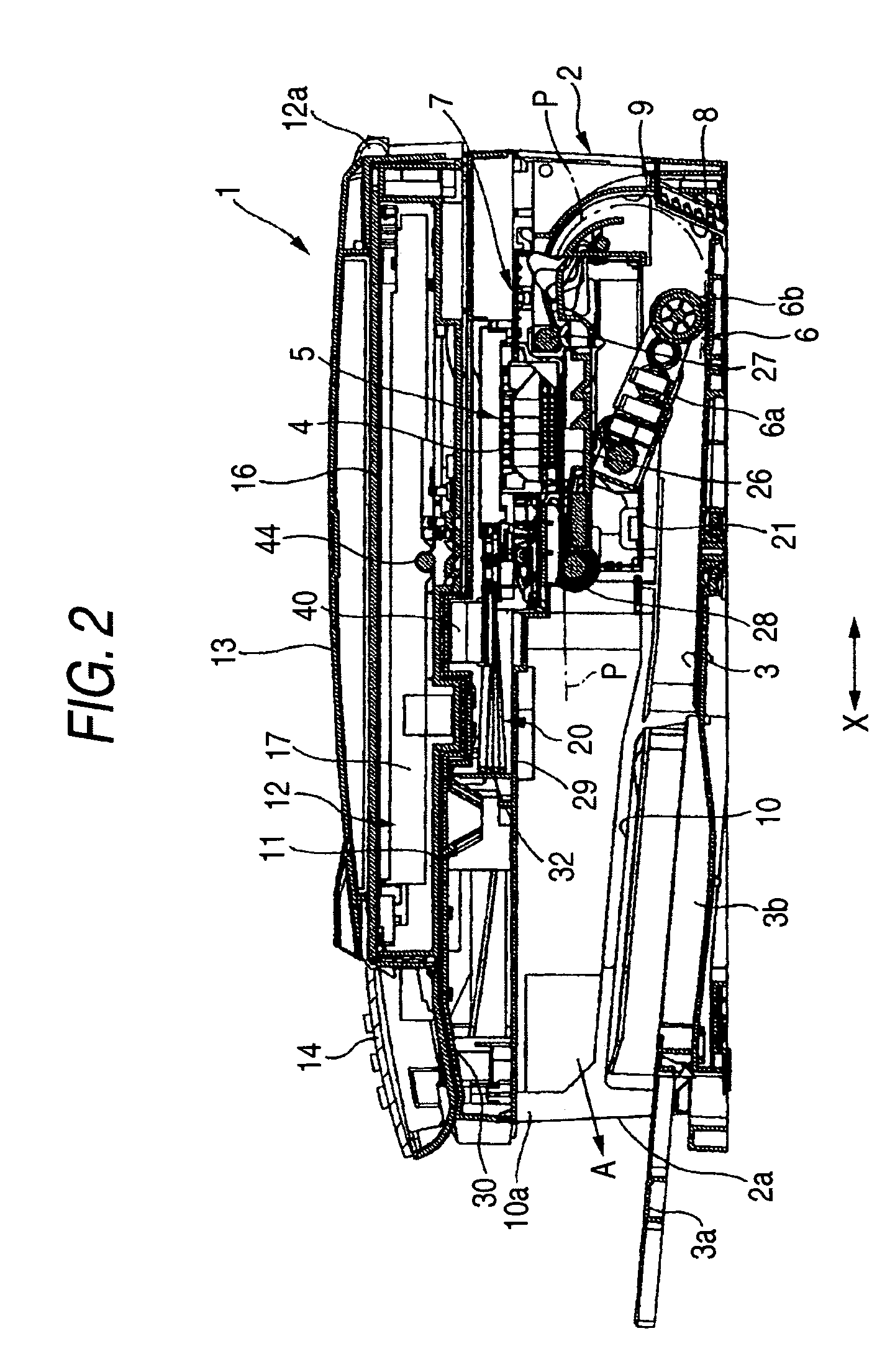
[0039]An image recording device 1 of the embodiment is a multi function device (MFD), to which the present invention is applied, having a printer function, a copying function, a scanner function, and a facsimile function. As shown in FIGS. 1 and 2, a paper feed cassette 3 is disposed at the bottom of a housing 2, which serves as a recording device main body, made from a synthetic resin, of the image recording device 1 and which is constituted of a synthetic resin injection molded article. The paper feed cassette 3 is an example of a tray which can be inserted through an opening 2a disposed in the front (on the left side in FIG. 2) of the bottom section of the housing 2.

[0040]In the embodiment, the paper feed cassette 3 is assumed to have a configuration such that paper P—which is cut into, for instance, A4-size, letter size, legal size, or postcard size, and which serves as a recording medium—can be stored...


PUM

PropertyMeasurementUnit
timeaaaaaaaaaa
friction coefficientaaaaaaaaaa
heightaaaaaaaaaa

Abstract

A recording medium feeder includes: a tray on which a plurality of recording medium are to be stacked; a feed roller that feeds the recording medium stacked on the tray; a first friction member provided on the tray and having high friction coefficient; and a second friction member provided on the tray at a position opposing the feed roller and having low friction coefficient that is lower than the friction coefficient of the first friction member, wherein the first friction member is configurable to be in one of positions of a protruded position in which a surface of the first friction member is protruded from a surface of the second friction member towards the feed roller and a retracted position in which the surface of the first friction member is arranged to be not higher than the surface of the second friction member.

Description

BACKGROUND OF THE INVENTION[0001]1. Field of the Invention[0002]The present invention relates to the configuration of a recording medium feeder for separating accumulated cut sheets (recording medium) one by one, thereby feeding the sheet to a recording section, or the like; and to the configuration of an image recording device of an inkjet type, or the like, including the recording medium feeder.[0003]2. Description of the Related Art[0004]An image recording device of related art, such as any of a variety of printers or facsimile machines, includes a paper feeder for feeding a plurality of sheets of paper (cut sheets, recording mediums) stacked (accumulated) on a hopper section by means of rotation of a paper feed roller (a rotary feeding member). As the paper feeder, that adopting a horizontal-stacking method in which a plurality of sheets are stacked horizontally, and that adopting an inclined-stacking method in which the same are stacked in a vertically inclined state, have been...

Claims


Application Information

Patent Timeline
Patent Type & Authority Patents(United States)
IPC IPC(8): B65H3/52B65H1/04B65H1/26B65H3/06
CPCB65H1/04B65H1/266B65H3/06B65H3/5223B65H2301/423245B65H2402/5441B65H2404/5311B65H2405/11161B65H2405/1118B65H3/0669B65H3/0684B65H2403/422B65H2403/481B65H2402/54
Inventor SHIOHARA, YUKIOASADA, TETSUO
Owner BROTHER KOGYO KK
Why Eureka
Try Eureka