Wafer container with tubular environmental control components

a technology of environmental control components and reticle pods, which is applied in the field of reticle pods and reticle containers, can solve the problems of insufficient optimal use of such structures, contamination of reticles in such containers, and high care and effort required for maintaining such clean rooms in a contaminant-free state, and achieves high coefficient of friction, easy retrofitting, and improved fluid flow characteristics

Active Publication Date: 2011-05-19
ENTEGRIS INC
View PDF16 Cites 44 Cited by
  • Summary
  • Abstract
  • Description
  • Claims
  • Application Information

AI Technical Summary

Benefits of technology

In particular embodiments, the tubular environmental control component has apertures either for exuding purge gas into the open interior of the container portion or for allowing absorbent media in the component to absorb vapors, including humidity from the interior of the container portion. A feature and advantage is that such apertures may be selectively obstructed to stop communication between the interior of the tubular component and the open interior of the wafer container. This is highly advantageous for washing the container so that filters, getters, or other contents of the tubular component can be protected from the washing fluids without removing the components. The obstruction may be by an elastomeric strip that seals the apertures as by a rigid slidably attached member that can cover and uncover the apertures. Moreover such selective blocking can be adjustable to change the size of the openings between the interior of the container portion and the interior of the tubular component.
A feature and advantage of certain embodiments is that the tubular component with apertures may be horizontally offset form the purge inlet connected thereto. This provides clearance with respect to the wafers. Moreover, positioning the discharge aperture in the tubular component back in the recess or compartment is believed to provide better fluid flow characteristics for the purge gas. Positioning the tubular components in the back recess provides the advantage of protection of the purge component from bumping or inadvertent contact.
A feature and advantage of certain embodiments is the methods of attachment of environmental control components in the rear compartments. These compartments reflect the interior structure formed by the pair of vertical external projections on the back wall of wafer containers that are utilized as feet or seating features when the container portion is rotated rearward ninety degrees. These internal compartments have walls that generally converge rearwardly. In a particular embodiment, a flexible elastomeric attachment member is secured intermediate the top of a tubular environmental control component and the polymer wall of the container portion. Such elastomeric attachment member secures the tower in place without apertures through the walls and optimally utilizes the high coefficient of friction between the polycarbonate container portion wall and the elastomeric material. The member may be shaped as a cap further providing the advantageous function of securing together elongate components that comprising the containment portion of tubular environmental control components. A tubular component may have such a member on both ends to utilize the high coefficient of friction and the compression of the elastomeric members to retain said tubular environmental control component within, totally or partially, the rearward compartment. In another embodiment a rigid bracket formed from metal or a rigid polymer may have spring teeth to wedge the bracket between opposing walls of the compartment wherein the teeth dig into the surface of the container portion wall. A feature and advantage of these attachment methods and structures is that the attachment utilizes the opposing walls for engagement of the attachment components without separate structure or fasteners that extend through walls of the wafer container. Therefore, wafer containers may be readily retrofitted with no modifications or reduced modifications to the product.
A feature and advantage of embodiments utilizing the tubular getter media is that a relatively high area of media is effectively exposed in a confined area in the wafer container. Moreover, the rear compartments work well for the tubular components that have no media and are utilized for pure purging.
A further feature and advantage of certain embodiments is that where purge gas is exhausted through the tower, the tubular getter media may be effectively recharged for periods when the environment therein is static.
A further feature and advantage of embodiments herein is that accommodation of the invention in existing configurations of 300 wafer containers requires minimal changes in such containers. A further feature and advantage is that aspects of the invention are highly suitable for larger wafer containers.

Problems solved by technology

However, maintenance of such “clean rooms” in a contaminant free state can require a great deal of care and effort, particularly during processing of the materials.
It has been observed that contamination of reticles in such containers can be caused not only by discrete particles but also by hazing occurring on wafers or reticles.
Problems associated with such structures and optimal use of such structures has not been adequately addressed.
For example, the use of desiccants and vapor getters in substrate containers typically require removal or disassembly of same before washing and such substrate containers as the fluids utilized can destroy the media for filtering and / or vapor absorption.
Moreover, purge port plumbing within substrate containers is, aside from the media issues, difficult to clean and dry due to the enclosed areas used for transferring purge gases.
Particularly, problematic in cleaning are free standing towers such as disclosed in U.S. Pat. No. 6,042,651.
Moreover, such towers are subject to movement and potential dislocation due to their conventional positioning where they may be inadvertently contacted and their connection only at the base of the substrate container.
The use of discrete towers in a front opening pod, the use of more than one discharge tower, and the optimal placement and securement of discharge towers or tubular environmental control components has not heretofore been adequately considered and optimized to satisfactorily address reliability, haze, contamination and particulate control, and cleaning issues in front opening large diameter wafer containers.

Method used


Image

  • Wafer container with tubular environmental control components
  • Wafer container with tubular environmental control components
  • Wafer container with tubular environmental control components

Examples


Embodiment Construction

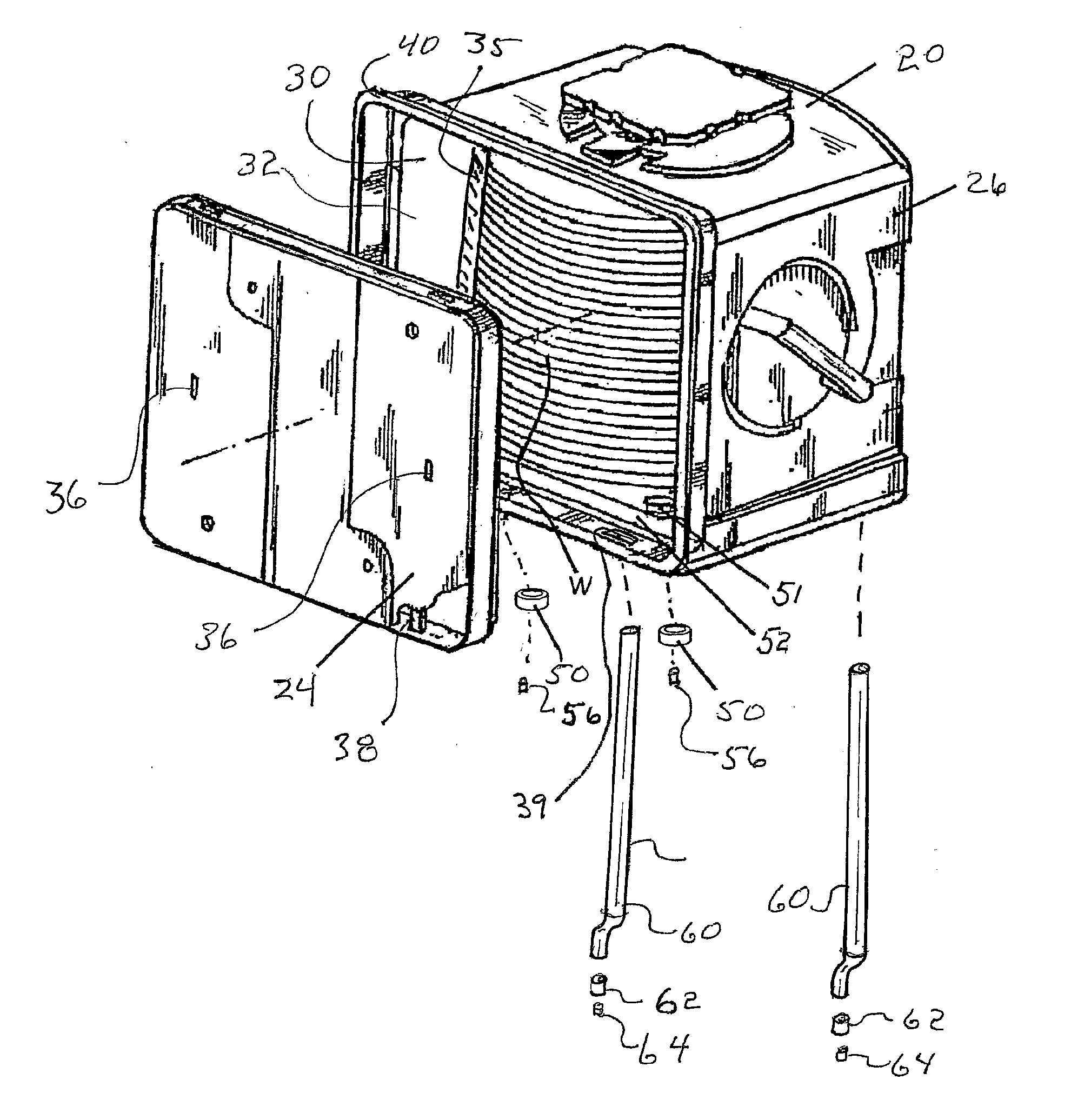
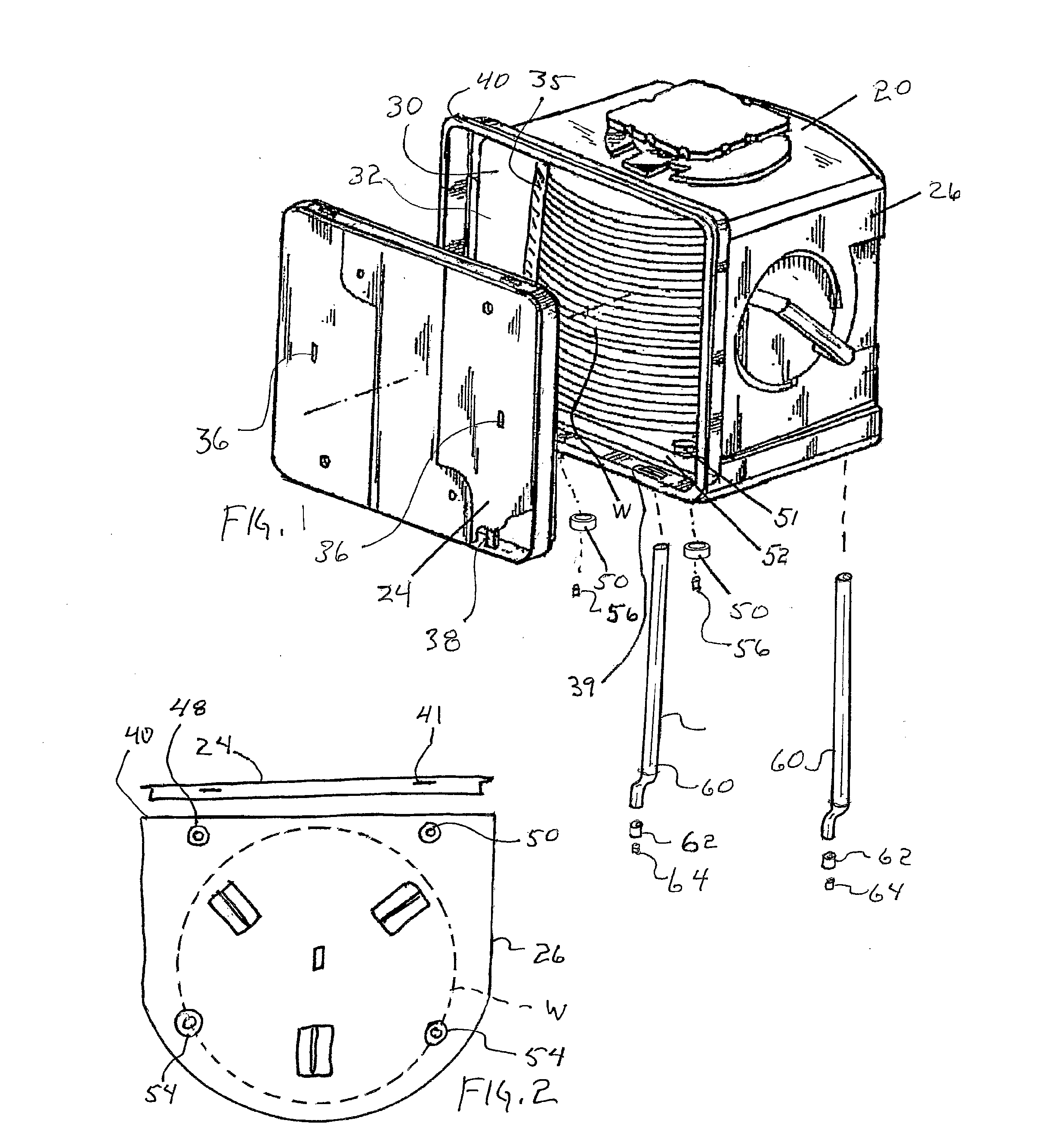
Referring to FIGS. 1 and 2, a front opening wafer container 20 is depicted and generally includes door 24 and container portion 26. Container portion 26 has front opening 30 leading into open interior 32 where a plurality of wafers W are retained on wafer shelves 35. Door 24 has key access holes 36 with latch mechanism 38 partially illustrated in the interior of the door enclosure with latch tips 41 that engage recesses 39 in the container portion door frame 40. The wafer container has purge capabilities with a pair of forward purge ports 48 with purge grommets 50 which are secured into grommet receiving structure 51 on the bottom 52 of the container portion and rearward purge ports 54. Check valves 56 may be inserted into the grommets to control the direction of purging gas fluid flow. Tubular environmental control components configured as purge towers 60 are illustrated which also may utilize grommets 62 and check valves 64. An exemplary location of purge ports is illustrated in F...


PUM


Abstract

A wafer container utilizes a rigid polymer tubular tower with slots and a “getter” therein for absorbing and filtering moisture and vapors within the wafer container. The tower preferably utilizes a purge grommet at the base of the container and may have a check valve therein to control the flow direction of gas (including air) into and out of the container and with respect to the tower. The tower is sealingly connected with the grommet. The tower may have a getter media piece rolled in an elongate circular fashion forming or shaped as a tube and disposed within the tower and may have axially extending. The media can provide active and/or passive filtration as well as having capabilities to be recharged. Front opening wafer containers for 300 mm sized wafers generally have a pair of recesses on each of the left and right side in the inside rear of the container portions. These recesses are preferably utilized for elongate towers, such towers extending substantially from a bottom wafer position to a top wafer position. In alternative embodiment, a tubular shape of getter material is exposed within the front opening container without containment of the getter other than at the ends. The tubular getter form is preferably supported at discrete locations to maximize exposure to the internal container environment. A blocker member can selectively close the apertures. An elastomeric cap can facilitate securement of the tubular component in the container portion.

Description

BACKGROUND OF THE INVENTIONWafer containers and reticle pods generally are sealed containers known as FOUPs (front opening unified pods), FOSBs (front opening shipping boxes), or SMIF (standard mechanical interface) pods. These containers provide a microenvironment to isolate and control the environment surrounding a wafers and substrates used in manufacturing integrated circuits, during storage, transport and processing of the materials. Processing of such materials traditionally has been carried out in a particulate free environment generally known as a “clean room”. However, maintenance of such “clean rooms” in a contaminant free state can require a great deal of care and effort, particularly during processing of the materials.The internal atmosphere of such microenvironments can be more readily controlled and maintained. Often, such containers are purgible with inert gas or clean dry air (CDA) or extra CDA. It has been observed that contamination of reticles in such containers c...

Claims


Application Information

Patent Timeline
Patent Type & Authority Applications(United States)
IPC IPC(8): B65D85/86
CPCH01L21/67393
Inventor WATSON, JAMES A.BURNS, JOHNFORBES, MARTIN I.FULLER, MATTHEW A.SMITH, MARK V.
Owner ENTEGRIS INC
Why Eureka
Try Eureka