Coolant system

Active Publication Date: 2014-05-01
JTEKT CORP +1
View PDF0 Cites 9 Cited by
  • Summary
  • Abstract
  • Description
  • Claims
  • Application Information

AI Technical Summary

Benefits of technology

[0007]The present invention has been made taking the circumstance like this into consideration, and an object thereof is

Problems solved by technology

On the other hand, the coolant being far from the pump in the reservoir is hard to be drawn by the pump.
However, in the aforementione

Method used


Image

  • Coolant system
  • Coolant system
  • Coolant system

Examples


Embodiment Construction

[0020](Construction of Coolant System)

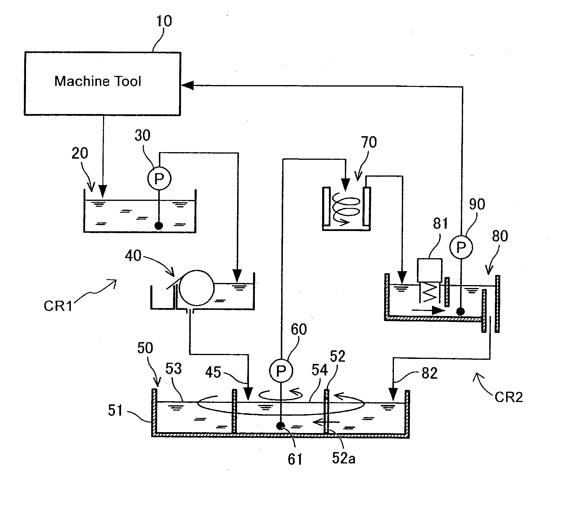
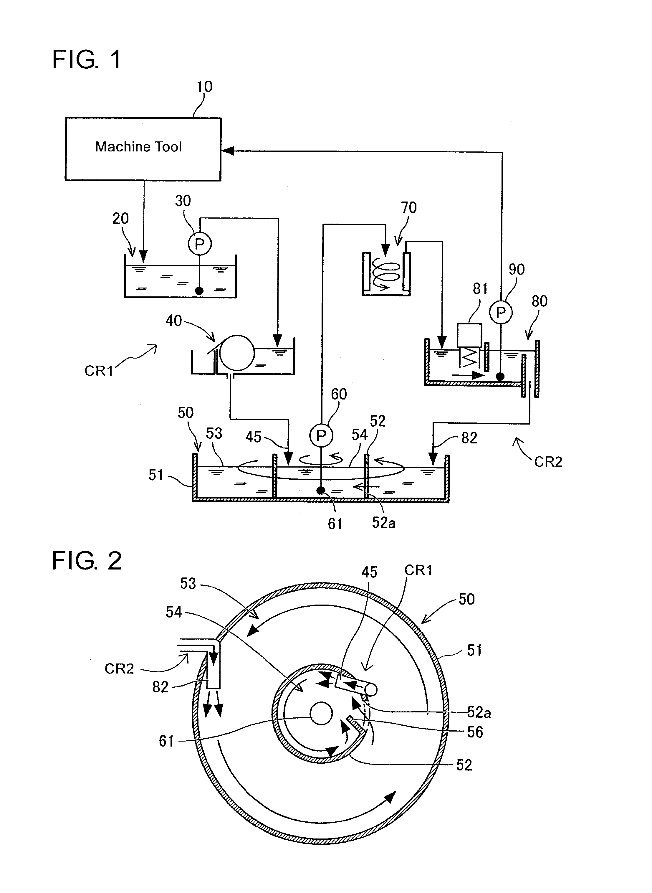
[0021]The system construction of a coolant system in the present embodiment will be described with reference to FIGS. 1 and 2. As shown in FIG. 1, the coolant system is a system for purifying dirty coolant having been used in a machine tool 10. In the coolant system, the dirty coolant is purified by being subjected to filtration at two stages, and the purified coolant is returned to the machine tool 10.

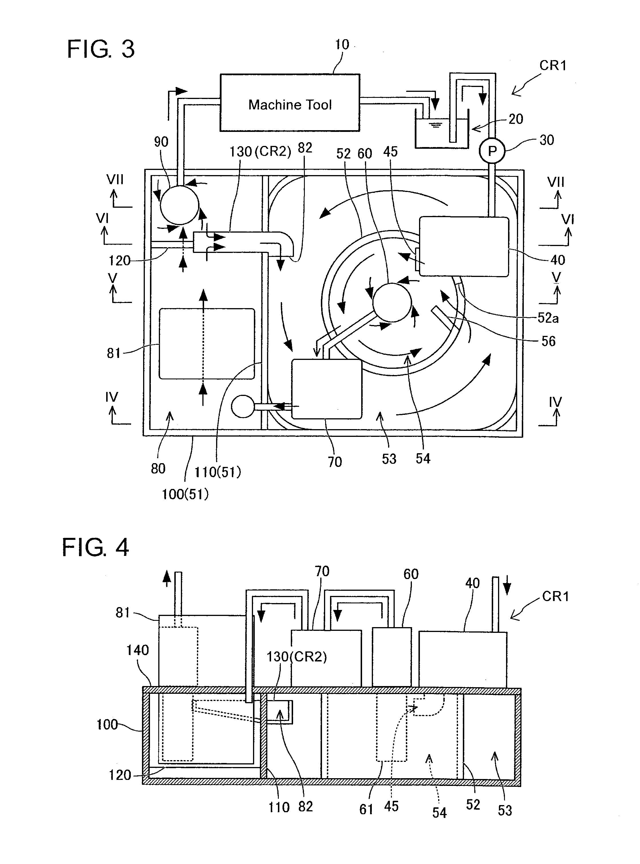
[0022]The coolant system is provided with a collecting reservoir 20, a pump 30, a primary filtering device 40, a primary reservoir 50, a pump 60, a secondary filtering device 70, a secondary reservoir 80, and a circulation pump 90. The collecting reservoir 20 collects the coolant discharged form the machine tool 10, that is, the coolant having been used for the machining in the machine tool 10. The coolant contains machining (cutting / grinding) chips, abrasive grains and the like.

[0023]A suction port of the pump 30 is arranged in the collecting res...


PUM

PropertyMeasurementUnit
Flow rateaaaaaaaaaa
Depthaaaaaaaaaa

Abstract

In a coolant system, the interior of a reservoir frame storing the coolant discharged from a machine tool is partitioned by a partition member into an outer peripheral coolant tub and a central coolant tub. The partition member is formed with a silt that extends in the depth direction to make the outer peripheral coolant tub communicate with the central coolant tub. A suction port of a pump that feeds the coolant in the central coolant tub to a filtering device is arranged in the central coolant tub. The coolant discharged from the machine tool is supplied to the central coolant tub without passing through the outer peripheral coolant tub. At least a part of the coolant filtered by the filtering device is supplied to the outer peripheral coolant tub without passing through the central coolant tub.

Description

INCORPORATION BY REFERENCE[0001]This application is based on and claims priority under 35 U.S.C. 119 with respect to Japanese Application No. 2012-238510 filed on Oct. 30, 2012, the entire content of which is incorporated herein by reference.BACKGROUND OF THE INVENTION[0002]1. Field of the Invention[0003]The present invention relates to a coolant system that filters and circulates coolant used in a machine tool.[0004]2. Discussion of the Related Art:[0005]Various coolant systems are described in JP2006-055981A, JP2003-175437A, WO2008 / 035551A, JP2012-045678A, and JP2012-125909A.[0006]In a coolant system, coolant is discharged from a machine tool to a reservoir and is fed by a pump from the reservoir to a filtering device. In the reservoir, the coolant around a suction port of the pump is drawn by the pump and is fed to the filtering device. On the other hand, the coolant being far from the pump in the reservoir is hard to be drawn by the pump. However, in the aforementioned coolant s...

Claims


Application Information

Patent Timeline
IPC IPC(8): B01D35/02
CPCB01D35/02B03C1/30B23Q11/1069B03C2201/18Y02P70/10
Inventor HORI, NOBUMITSUWADA, TETSUAKIMATSUMOTO, TETSUYAKAMEI, HIROTOKATO, SHIGEYUKI
Owner JTEKT CORP
Why Eureka
Try Eureka