A suction structure for pipe feeding

A catheter and guide rail technology, which is applied to conveyor objects, transportation and packaging, etc., can solve problems such as catheter deformation, and achieve the effects of preventing deformation under pressure, reliably sucking, and avoiding rigid pressure.

Active Publication Date: 2016-11-30
MAIDER MEDICAL IND EQUIP
View PDF6 Cites 0 Cited by
  • Summary
  • Abstract
  • Description
  • Claims
  • Application Information

AI Technical Summary

Problems solved by technology

[0005] The present invention aims at the above-mentioned problems existing in the prior art, and provides a suction structure for feeding tubes. The technical problem to be solved by the present invention is: how to accurately and reliably suck up the tubes and prevent the tubes from being deformed

Method used


Image

  • A suction structure for pipe feeding
  • A suction structure for pipe feeding
  • A suction structure for pipe feeding

Examples


Embodiment 1

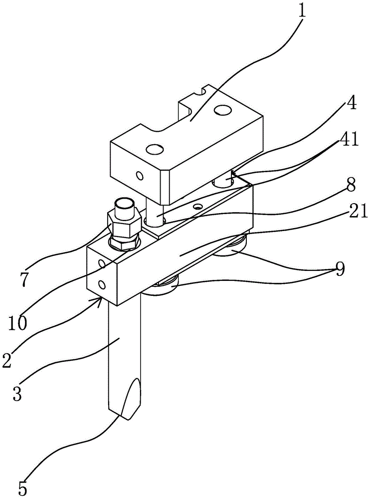
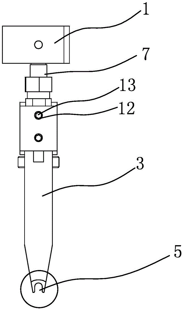
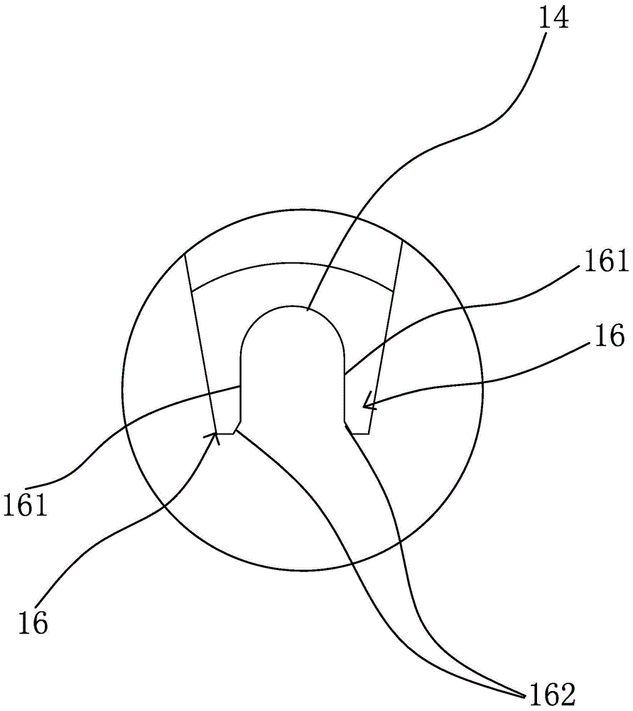
[0032] like Figure 1 to Figure 6As shown, the suction structure adopts the suction method to take and move the components of the catheter of the infusion set, so as to avoid the direct mechanical contact pressure pressing the catheter to deform it when the catheter is clamped. The suction structure in this embodiment includes a mounting seat 1 and a gas cylinder. The claw lever 3 is provided with a sliding mechanism 4 between the mounting base 1 and the air claw lever 3 which can make the air claw lever 3 slide up and down in the vertical direction. The lower end of 3 has an arc-shaped concave claw 5, and the air claw rod 3 has a ventilation hole 6 that communicates with the claw 5. The claw 5 is composed of two symmetrical claw pieces 16, and the outer side of the claw piece 16 is Inclined surface 15 sloping from outside to inside.

[0033] like figure 1 and figure 2 As shown, the counterweight structure 2 is a counterweight block 21, the sliding mechanism 4 includes a v...

Embodiment 2

[0037] like Figure 7 As shown, this embodiment is roughly the same as the first embodiment, the difference lies in that, as another kind of counterweight structure 2 in this embodiment, the counterweight structure 2 is a section on the air gripper rod 3, and the sliding mechanism 4 includes a The guide hole 44 on the mounting base 1, the air gripper rod 3 is arranged in the guide hole 44 and is slidably connected with the guide hole 44, and the counterweight structure 2 is used as a section on the air gripper rod 3, which simplifies the structure. The force of the rod 3 is more stable and even, which is convenient for separating the accumulated conduits.

Embodiment 3

[0039] like Figure 8 As shown, this embodiment is roughly the same as the first embodiment, the difference is that, as another guide rail structure in this embodiment, the guide rail is a rail 42 fixed on the side wall of the mounting seat 1, and the side wall of the counterweight block is provided with a rail 42. There are guide grooves 43, the rails 41 are arranged in the corresponding guide grooves 43, and the up and down sliding of the air gripper rod 3 is realized through the cooperation of the guide grooves 43 and the rails 42. Such cooperation makes the position of the air gripper rod 3 stable, without shaking and turn. Of course, the positions of the guide groove 43 and the rail 42 can be interchanged, that is, the guide groove 43 is provided on the side wall of the mounting base 1 , and the rail 42 is provided on the side wall of the counterweight block 21 .


PUM


Abstract

The invention provides a suction structure for catheter feeding, and belongs to the technical field of mechanical devices. The suction structure for catheter feeding solves the technical problem that existing infusion set catheters are prone to deforming in the transfer process. The suction structure comprises an installing base and a pneumatic claw rod. A sliding mechanism which can make the pneumatic claw rod slide up and down in the vertical direction is arranged between the installing base and the pneumatic claw rod, a balance weight structure is fixedly connected to the pneumatic claw rod, an arc-shaped concave claw opening is formed in the lower end of the pneumatic claw rod, an air hole communicated with the claw opening is formed in the pneumatic claw rod, the claw opening is composed of two symmetrical claw pieces, and the outer side face of each claw piece is a slope which inclines from outside to inside. According to the suction structure for catheter feeding, the claw pieces of the claw opening form a wedge, and can be easily inserted into cumulate catheters to separate the catheters which cling to one another so that a target catheter can smoothly enter the claw opening, and the purpose of sucking catheters rapidly, accurately and reliably is achieved.

Description

technical field [0001] The invention belongs to the technical field of medical equipment manufacturing equipment, and relates to a production and assembly device for a catheter of an infusion set, in particular to a suction structure for feeding the catheter. Background technique [0002] The infusion set is an auxiliary device commonly used in medical treatment, mainly used for intravenous infusion. It is generally composed of venous needle, protective cap, medicinal liquid filter, flow rate regulator, drip pot, cork puncture, and air intake pipe air filter connection. The components are connected by a conduit through which the medicinal liquid flows. In the production of the infusion set, the catheter is connected and assembled with the various components in sequence. When the conduits are assembled in different stations, the conduits need to be moved to the assembly station—that is, the conduits are loaded. The feeding of the duct usually has the grab type, the suction...

Claims


Application Information

Patent Timeline
Patent Type & Authority Patents(China)
IPC IPC(8): B65G47/90
Inventor 林军华
Owner MAIDER MEDICAL IND EQUIP
Why Eureka
Try Eureka