Image pickup apparatus

Active Publication Date: 2007-08-09
PANASONIC CORP
View PDF7 Cites 6 Cited by
  • Summary
  • Abstract
  • Description
  • Claims
  • Application Information

AI Technical Summary

Benefits of technology

[0009]With the image pickup apparatus of the pre

Problems solved by technology

However, the configuration disclosed in the patent document 1 has the following problem.
When a user operates each switch, the finger of the user has to be moved to an upper por

Method used


Image

  • Image pickup apparatus
  • Image pickup apparatus
  • Image pickup apparatus

Examples


embodiment 1

[0017][1. Configuration of Image Pickup Apparatus]

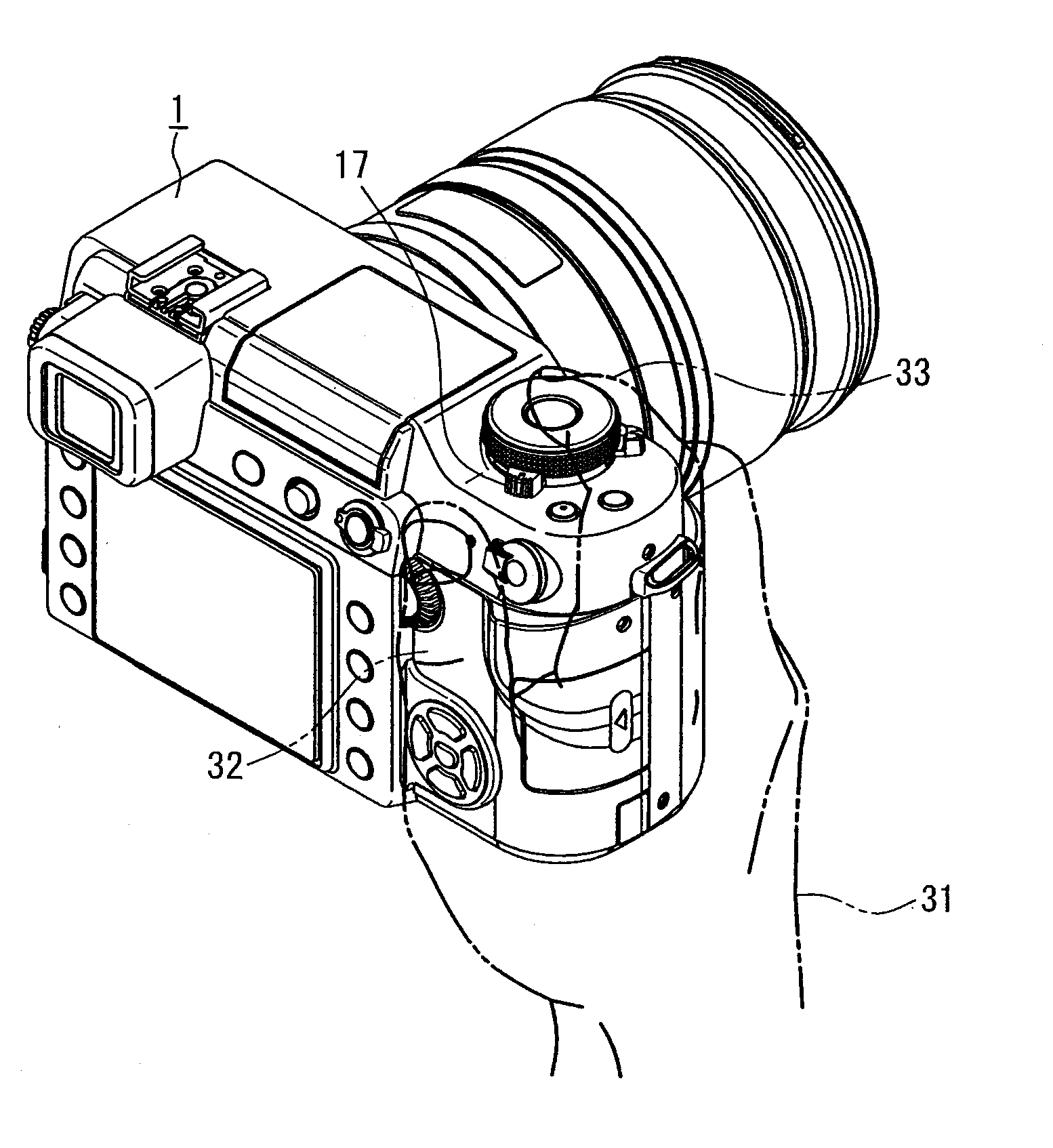
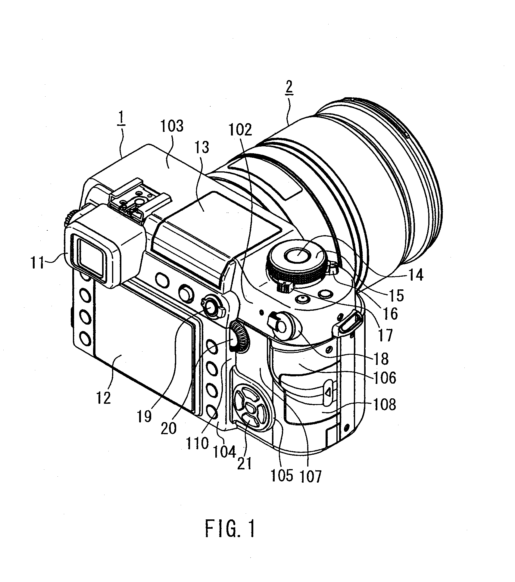
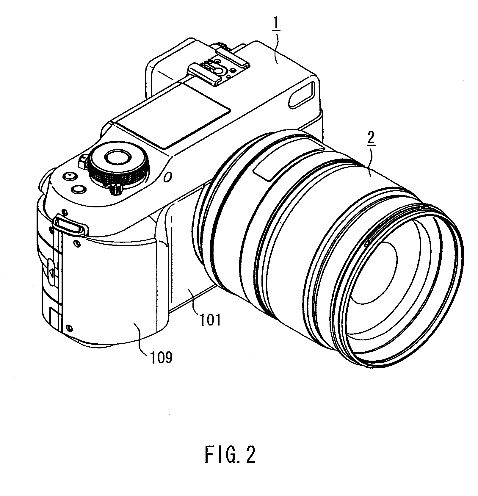
[0018]FIG. 1 is a perspective view of an image pickup apparatus according to Embodiment 1, which illustrates an appearance of the same viewed from the user side. FIG. 2 is a perspective view of the image pickup apparatus, which illustrates an appearance of the same viewed from a subject side. FIG. 3 is a side view of the image pickup apparatus, which illustrates the appearance of the same viewed from the user side. It should be noted that the present embodiment is described by referring to a digital single-lens reflex camera as an example of the image pickup apparatus as shown in the drawings.

[0019]As shown in FIG. 1, the image pickup apparatus principally is composed of a main body 1 and a lens barrel 2.

[0020]The main body 1 incorporates: an image pickup element that forms an optical image that entered through lenses in the lens barrel 2, converts the same to electric signals, and outputs the same; a signal processing circuit for ge...


PUM


Abstract

An image pickup apparatus of the present invention includes a main body 1 incorporating an image pickup element, an operation part that is placed on the main body 1 and can be operated by a user, and a seventh surface 107 provided on the main body 1, on which, when the user takes a picture while holding the main body 1, the thumb of the hand holding the main body 1 can be left in a stand-by state. The operation part includes rotation operation parts that are placed in the vicinity of the seventh surface 107 and are rotatable, and the rotation operation parts are arranged so that at least a part of the same faces the seventh surface 107. With this, a movement amount of the fingers of the user is reduced, whereby the operability is improved.

Description

BACKGROUND OF THE INVENTION[0001]1. Field of the Invention[0002]The present invention relates to an image pickup apparatus such as a digital still camera.[0003]2. Description of Related Art[0004]In recent years, digital still cameras have been devised in which arrangements of operation parts such as buttons and levers are improved so that the operability thereof is improved.[0005]For example, the patent document 1 (JP 3631226 B) discloses a configuration in which switches are arranged in a manner such that a user is allowed to operate them more easily. More specifically, as shown in FIGS. 5 and 6 of the patent document 1, in a video camera 100, a zoom switch 19c is arranged at a position such that the switch is operable with the index finger of a user, while a mode switching switch 19a, an image pickup start / stop switch 19b, and a joy stick 10 are arranged at positions such that these are operable with the thumb of the user. With this configuration, the switches can be operated with...

Claims


Application Information

Patent Timeline
IPC IPC(8): H04N5/222
CPCH04N5/2251H04N23/50
Inventor OGINO, YUSHI
Owner PANASONIC CORP
Why Eureka
Try Eureka