Zoom lens system with vibration reduction function

a technology of zoom lens and function, applied in the field of zoom lens system, can solve the problems of large vibration reduction mechanism, difficult to make the zoom lens system small, complicated zooming mechanism,

Inactive Publication Date: 2007-08-09
NIKON CORP
View PDF11 Cites 20 Cited by
  • Summary
  • Abstract
  • Description
  • Claims
  • Application Information

AI Technical Summary

Problems solved by technology

However, in any one of disclosed examples, an effective diameter of a vibration reduction lens group is large about 25 mm or more, so that a vibration reduction mechanism becomes large.
Accordingly, it becomes difficult to make the zoom lens system small.
Moreover, the number of lens groups of a zoom lens system is five or more, so that a zooming mechanism becomes complicated.

Method used


Image

  • Zoom lens system with vibration reduction function
  • Zoom lens system with vibration reduction function
  • Zoom lens system with vibration reduction function

Examples


example 1

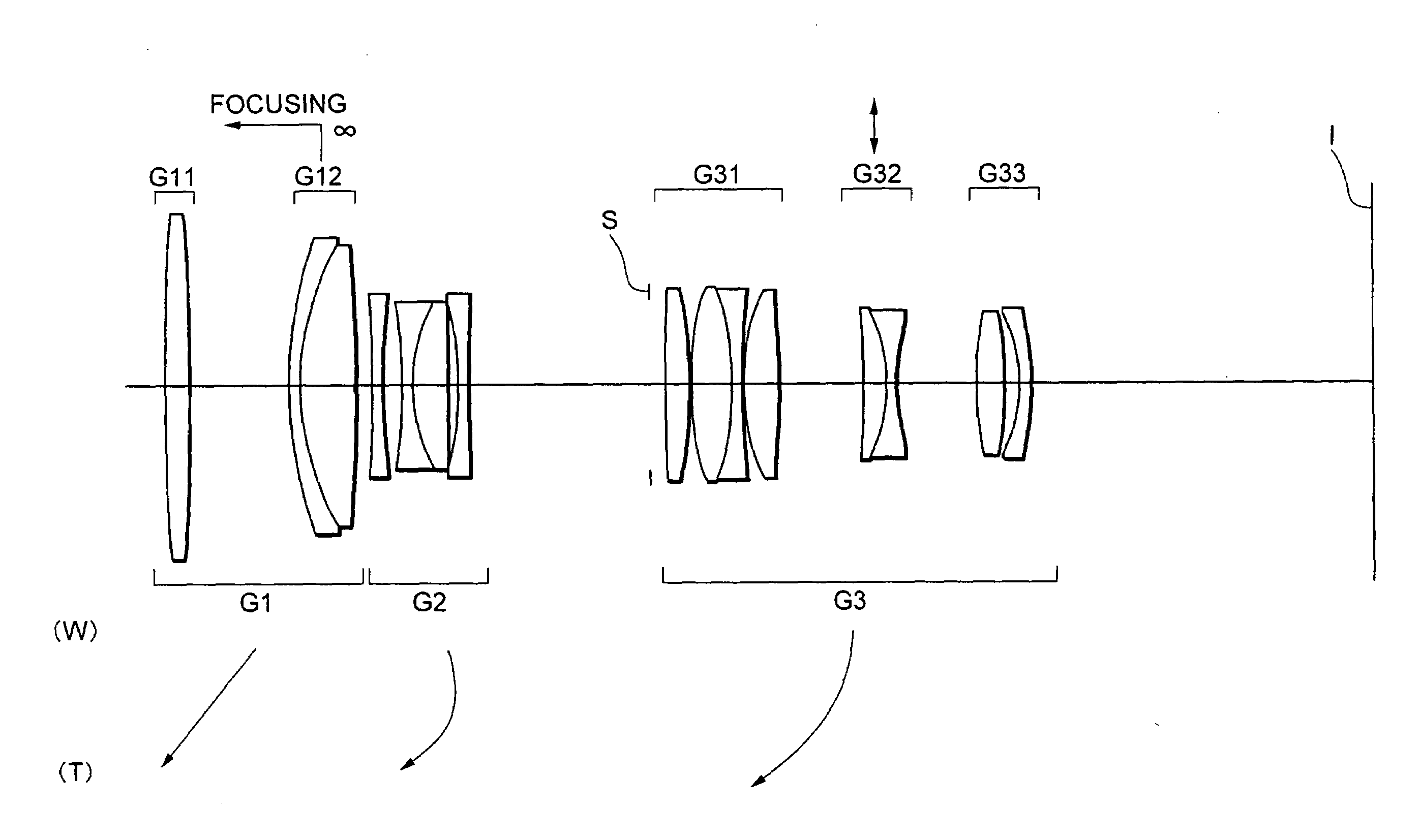
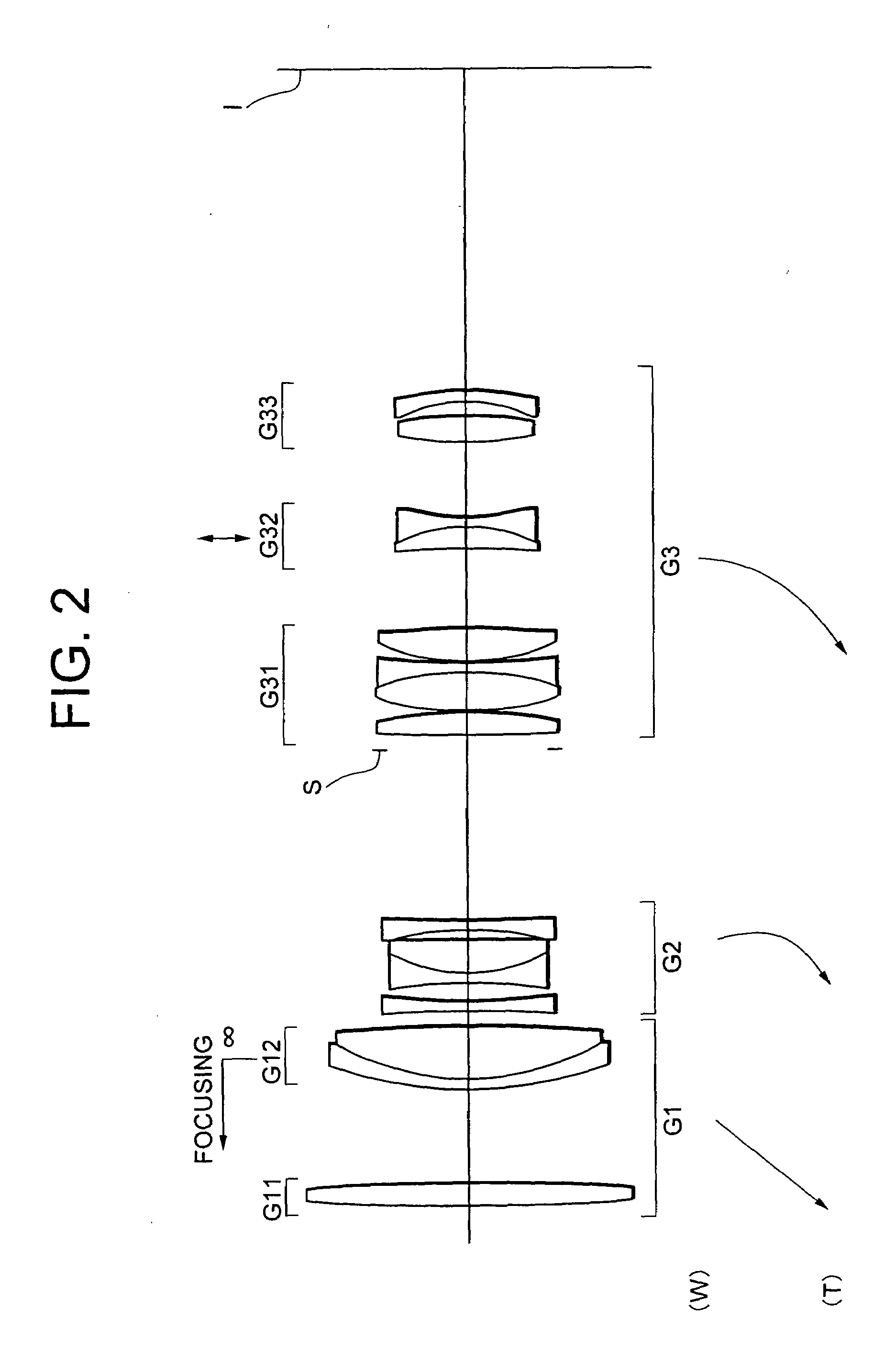
[0065]FIG. 2 is a diagram showing a lens configuration of a zoom lens system with a vibration reduction function according to Example 1.

[0066]In FIG. 2, the zoom lens system with a vibration reduction function is composed of, in order from an object, a first lens group G1 having positive refractive power, a second lens group G2 having negative refractive power, and a third lens group G3 having positive refractive power. Upon zooming from a wide-angle end state (W) to a telephoto end state (T), the first lens group G1 and the third lens group G3 are moved to the object, and the second lens group G2 is moved at first to the image plane I then to the object such that a distance between the first lens group G1 and the second lens group G2 increases, and a distance between the second lens group G2 and the third lens group G3 decreases.

[0067]The first lens group G1 is composed of, in order from the object, an 11 lens group G11 having positive refractive power and a 12 lens group G12 havin...

example 2

[0081]FIG. 6 is a diagram showing a lens configuration of a zoom lens system with a vibration reduction function according to Example 2.

[0082]In FIG. 6, the zoom lens system with a vibration reduction function is composed of, in order from an object, a first lens group G1 having positive refractive power, a second lens group G2 having negative refractive power, and a third lens group G3 having positive refractive power. Upon zooming from a wide-angle end state (W) to a telephoto end state (T), the first lens group G1 and the third lens group G3 are moved to the object, and the second lens group G2 is moved at first to the image plane I then to the object such that a distance between the first lens group G1 and the second lens group G2 increases, and a distance between the second lens group G2 and the third lens group G3 decreases.

[0083]The first lens group G1 is composed of, in order from the object, an 11 lens group G11 having positive refractive power and a 12 lens group G12 havin...

example 3

[0093]FIG. 10 is a diagram showing a lens configuration of a zoom lens system with a vibration reduction function according to Example 3.

[0094]In FIG. 10, the zoom lens system with a vibration reduction function is composed of, in order from an object, a first lens group G1 having positive refractive power, a second lens group G2 having negative refractive power, and a third lens group G3 having positive refractive power. Upon zooming from a wide-angle end state (W) to a telephoto end state (T), the first lens group G1 and the third lens group G3 are moved to the object, and the second lens group G2 is moved at first to the image plane I then to the object such that a distance between the first lens group G1 and the second lens group G2 increases, and a distance between the second lens group G2 and the third lens group G3 decreases.

[0095]The first lens group G1 is composed of, in order from the object, an 11 lens group G11 having positive refractive power and a 12 lens group G12 hav...


PUM


Abstract

Providing a compact zoom lens system suitable for a single-lens reflex camera using a solid-state imaging device, having a zoom ratio of about 3.5 or more, an angle of view of 29° or more in a wide-angle end, and a vibration reduction function. The system includes, in order from an object, a first group having positive power, a second group having negative power, and a third group having positive power. Upon zooming from a wide-angle end to a telephoto end, a distance between the first and second groups increases, and a distance between the second and third groups decreases. The third group consists of, in order from the object, a 31 group having positive power, a 32 group having negative power, and a 33 group. Only the 32 group is moved perpendicularly to an optical axis for correcting an image blur upon generating a camera shake. Given conditions are satisfied.

Description

[0001]The disclosure of the following priority application is herein incorporated by reference:[0002]Japanese Patent Application No. 2006-027323 filed on Feb. 3, 2006.BACKGROUND OF THE INVENTION[0003]1. Field of the Invention[0004]The present invention relates to a zoom lens system suitable for a single-lens reflex camera using a film or a solid-state imaging device.[0005]2. Related Background Art[0006]There have been proposed zoom lens systems having a vibration reduction function with a zoom ratio of about four in such as Japanese Paten Application Laid-Open Nos. 8-62541 and 10-133114.[0007]Examples disclosed in Japanese Patent Application Laid-Open No. 8-62541 are a positive-negative-positive-positive-negative five-lens-group zoom lens system or a positive-negative-positive-negative-positive-negative six-lens-group zoom lens system, in which a second lens group with negative refractive power is moved for vibration reduction.[0008]An example disclosed in Japanese Patent[0009]Appli...

Claims


Application Information

Patent Timeline
Patent Type & Authority Applications(United States)
IPC IPC(8): G02B27/64G02B7/02
CPCG02B27/646G02B15/173
Inventor MIZUGUCHI, KEIKO
Owner NIKON CORP
Why Eureka
Try Eureka