Remote controlled locking electroshock stun device and methods of use

Active Publication Date: 2007-08-09
MYERS STEVEN B
View PDF3 Cites 21 Cited by
  • Summary
  • Abstract
  • Description
  • Claims
  • Application Information

AI Technical Summary

Benefits of technology

[0006] What is needed is a means by which an individual under arrest, or a large number of individuals under arrest, may be non-lethally controlled by law enforcement officers while in public situations, while allowing that person, or persons, to maintain their Constitutional presumption of innocence when in a court of law or in public locations. It is also necessary to achieve a means by which such persons can be controlled and pacified quickly, effectively and in a non-lethal way in public situations, without providing the ability for those persons to remove the means of control and use it against a law enforcement officer or a member of the public. Such means should also provide a means by which a small number of law enforcement officers may, simultaneously and non-lethally, control a large number of persons under arrest without placing themselves or members of the public at risk of harm.
[0007] It is therefore an object of the present invention to provide a fully automated, remote controlled power source for administering a non-lethal, pulsating, incapacitating electric shock to a person at a specific point of contact, in combination with a remote control radio transmitter that is operable to deliver an operational signal to the power source to trigger the electric shock. In some embodiments, the power source is a single, small unit capable of being placed directly onto the body of a wearer in any number of discreet areas, such as the wrist, ankle, upper arm, or other areas where it may be hidden beneath clothing. The power source includes a locking mechanism configured to hold the power source securely to the wearer at the desired location, which mechanism is incapable of being unlocked and removed without a key. In some embodiments, the power source is operable to deliver a low-level electric shock to the wearer, while in other embodiments, the power source is operable to deliver a high-level electric shock, and in still other embodiments, the power source is operable to deliver an electric shock that is in between the former levels. The electric shock delivered by the power source is therefore sufficiently scalable so as to be configured to deliver any voltage to the wearer from approximately 40,000 volts up to approximately 80,000 volts. In all embodiments, the power source is configured to deliver an electric shock that is sufficient to immobilize the wearer, even through layers of clothing such as socks or shirt sleeves, without being lethal.
[0010] Also in some embodiments, the power source includes a banded, magnetically operated, locking mechanism with a ratchet or cog band that serves to hold the power source in place at the desired location on the wearer. In that regard, the locking mechanism also serves to hold the electrodes securely in place and ensures sufficient contact with the wearer for delivery of the shock. As described in greater detail below, the locking mechanism features a pawl that, when engaged, is held in place at any one of a plurality of locations along a ratchet or cog band by a plurality of magnets and which serves to restrict the motion of the band in a direction that would loosen it from the wearer's body. The pawl is automatically activated when the band is inserted into the appropriate location in the power source and remains activated until such time as a key of the proper configuration is inserted into the power source and turned in such a way so as to release the magnets holding the pawl in place, thereby releasing the locking mechanism.

Problems solved by technology

For example, it is often unnecessary for such officers to utilize deadly force to control a person under arrest, making the use of firearms undesirable in many instances where control is necessary, especially when in a crowded public area.
Other conventional weapons, such as clubs, pepper spray and Taser-type electroshock weapons, which are effective means of control in many situations, are wholly dependent upon the skill of the person using them and may also be impractical or impossible to use in certain crowded public situations.
Moreover, the officer using these other conventional weapons must be relatively close to the person under arrest in order for them to be effective, which presents a danger that they will be taken away from, and used against, the officer or turned on a member of the public.
Additionally, it may become necessary for an enforcement officer to physically overpower a person under arrest in order to regain control over that person, which can result in injuries to that person that are unintended by the officer, as well as injuries to the officer and to bystanders, all as unintended effects of the need to physically overpower such a person.
An additional challenge for law enforcement officers arises when transporting large numbers of persons under arrest to and through public areas.
There is a need to maintain control over each of these persons during transport, but it is often undesirable or impractical to have an equal number of guarding officers as persons being transported.
Similar control problems as those described above can arise in these situations, as it may be impractical to place each person in restraints or brightly colored uniforms, and it may be impossible for the outnumbered officers to maintain control of these persons in the event the same becomes necessary.
The power source includes a locking mechanism configured to hold the power source securely to the wearer at the desired location, which mechanism is incapable of being unlocked and removed without a key.

Method used


Image

  • Remote controlled locking electroshock stun device and methods of use
  • Remote controlled locking electroshock stun device and methods of use
  • Remote controlled locking electroshock stun device and methods of use

Examples


Embodiment Construction

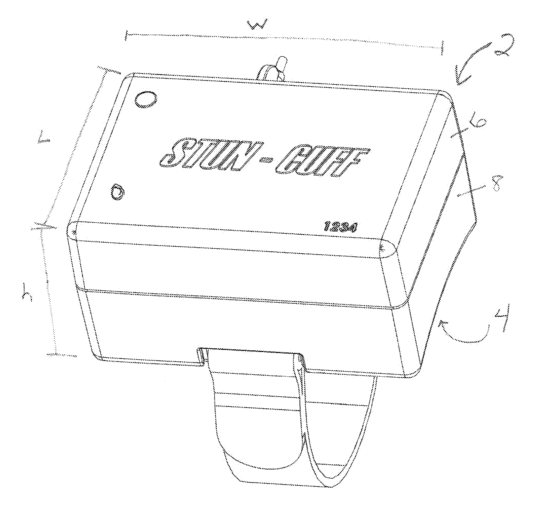
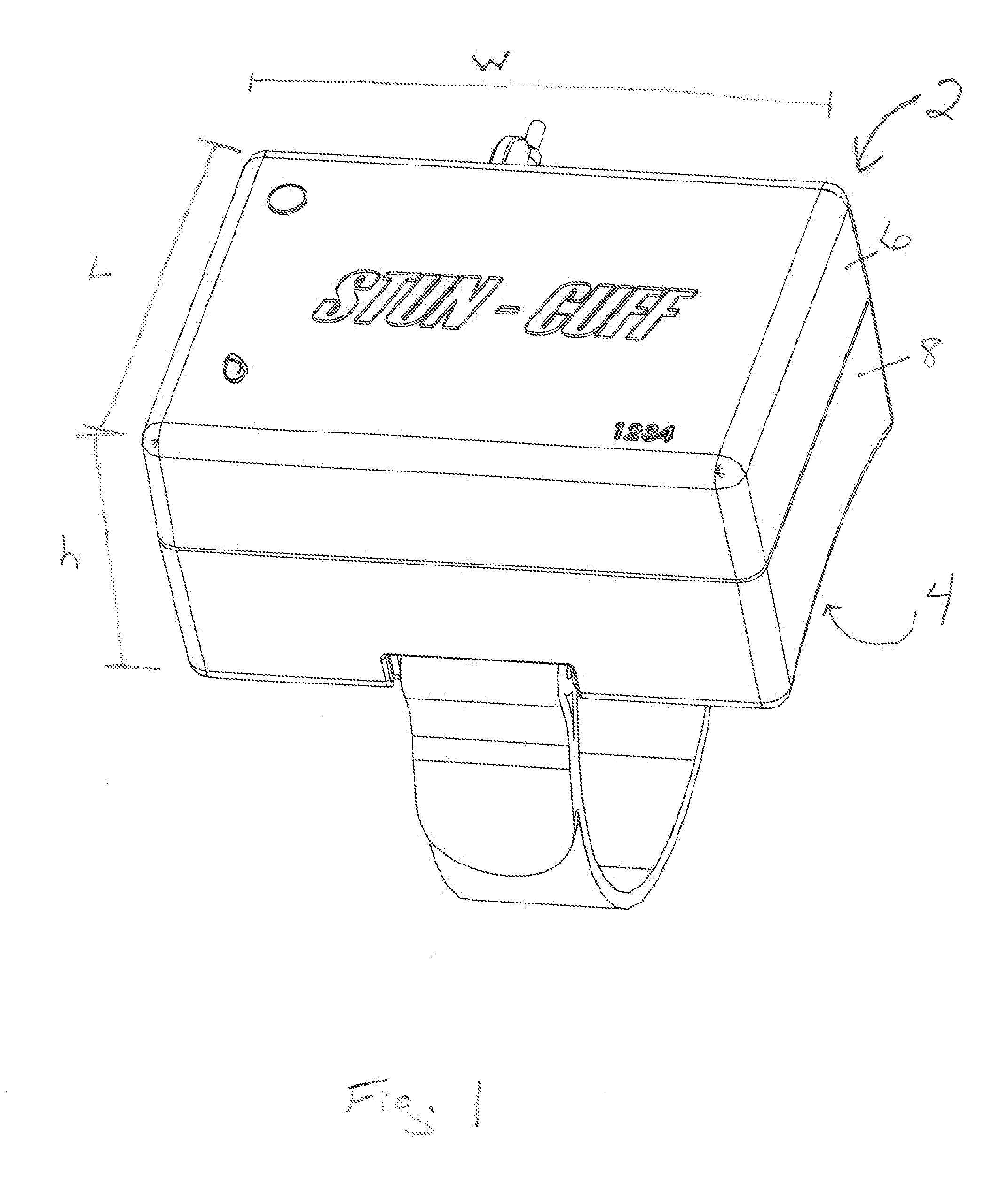
[0019] Referring initially to FIG. 1, a fully automated, remote controlled portable power source 2 for administering a non-lethal, pulsating, incapacitating electric shock to a person according to certain embodiments of the present invention is provided. The power source 2 is configured to be placed directly onto the body of a wearer in any number of discreet areas, such as the wrist, ankle, upper arm, or other areas where it may be hidden beneath clothing. Therefore, the power source 2 is preferably small enough in scale so as to fit over the hands and / or feet, and thereby be secured onto the ankles, arms, and / or wrists, of the average person, while remaining sufficiently low in profile so as to remain hidden under clothing, if so desired. In the presently preferred embodiment, the power source 2 has a length “L” of approximately 2 and 3 / 16 inches, a height “h” of approximately 1 and ⅝ inches, and a width “w” of approximately 3 and 3 / 16 inches and weighs less than about 16 ounces. ...


PUM


Abstract

An apparatus for administering an incapacitating electric shock to a person is provided, which comprises a portable power source, at least one pair of electrodes operatively associated with the power source and that are configured to deliver an electric shock to the person's body, a locking mechanism configured to secure the electrodes at a desired position on said person's body and a remote control capable of generating and transmitting a signal to the power source that triggers the electric shock. The apparatus is operable such that the remote control may trigger an electric shock in a single power source, or in a plurality of power sources.

Description

CROSS REFERENCE TO RELATED APPLICATIONS [0001] The present application claims the benefits of U.S. patent application Ser. No. 11 / 117,029 filed on Apr. 29, 2005, entitled “REMOTE CONTROLLED: LOCKING WRIST AND / OR ANKLE INCAPACITATING ELECTROSHOCK STUN BRACELET FOR PRISONER CONTROL” and U.S. patent application Ser. No. 11 / 294,205 filed on Dec. 6, 2005, entitled “LOCKING MECHANISM FOR USE WITH RATCHET OR COG STRAP,” The contents of each application are incorporated herein in their entirety.FIELD OF THE INVENTION [0002] The present invention generally relates to devices and methods for administering an electric shock to a target. More specifically, embodiments of the present invention provide a fully automated, remote controlled power source for administering a non-lethal, pulsating, incapacitating electric shock to a person at a specific point of contact. BACKGROUND OF THE INVENTION [0003] In law enforcement it is often necessary for enforcement officers to be able to control persons u...

Claims


Application Information

Patent Timeline
IPC IPC(8): F41B15/04
CPCF41H13/0018
Inventor MYERS, STEVEN B.
Owner MYERS STEVEN B
Why Eureka
Try Eureka