Projection optical system and projection-type image display apparatus

a projection optical system and image display technology, applied in the field of new projection optical system and new projection type image display apparatus, can solve the problems of increased sag amount, difficult manufacture of convex reflectors, and inability to achieve the effect of sufficient optical performan

Active Publication Date: 2007-08-09
SONY CORP
View PDF10 Cites 53 Cited by
  • Summary
  • Abstract
  • Description
  • Claims
  • Application Information

AI Technical Summary

Benefits of technology

[0020] In the projection optical system according to the invention, the light beam travels from the center of the primary image surface to the center of the secondary image surface and crosses the optical axis of the first optical system. The light beam is then reflected on the concave reflector, crosses the optical axis again, and reaches the secondary image surface. Following this light path, the first optical system once forms an intermediate imaging surface. The concave reflector is disposed after the intermediate imaging surface to form an image on the secondary image surface again. There is no need for a large concave reflector. It is possible to provide a large display that is appropriately corrected for aberration and exhibits sufficient optical performance.

Problems solved by technology

The projection optical system inevitably tends to enlarge the convex reflector f and increase the sag amount.
This not only makes the manufacture of convex reflectors difficult, but also heightens a display bottom portion (see reference symbol e in FIG. 62).
Since only reflectors are used to configure the system, however, the system tends to be very susceptive to the surface accuracy and the assembly accuracy of each reflector and increase manufacturing costs.
Increasing a projection angle for a lower profile enlarges the reflectors, especially the last reflector l, making the manufacture of reflectors difficult.
Applying this projection optical system to a rear projection television still leaves a difficulty in miniaturizing the bottom of the display.
The projection optical system tends to be very susceptive to the surface accuracy and the assembly accuracy, make the manufacture difficult, and increase manufacturing costs.

Method used


Image

  • Projection optical system and projection-type image display apparatus
  • Projection optical system and projection-type image display apparatus
  • Projection optical system and projection-type image display apparatus

Examples


first embodiment

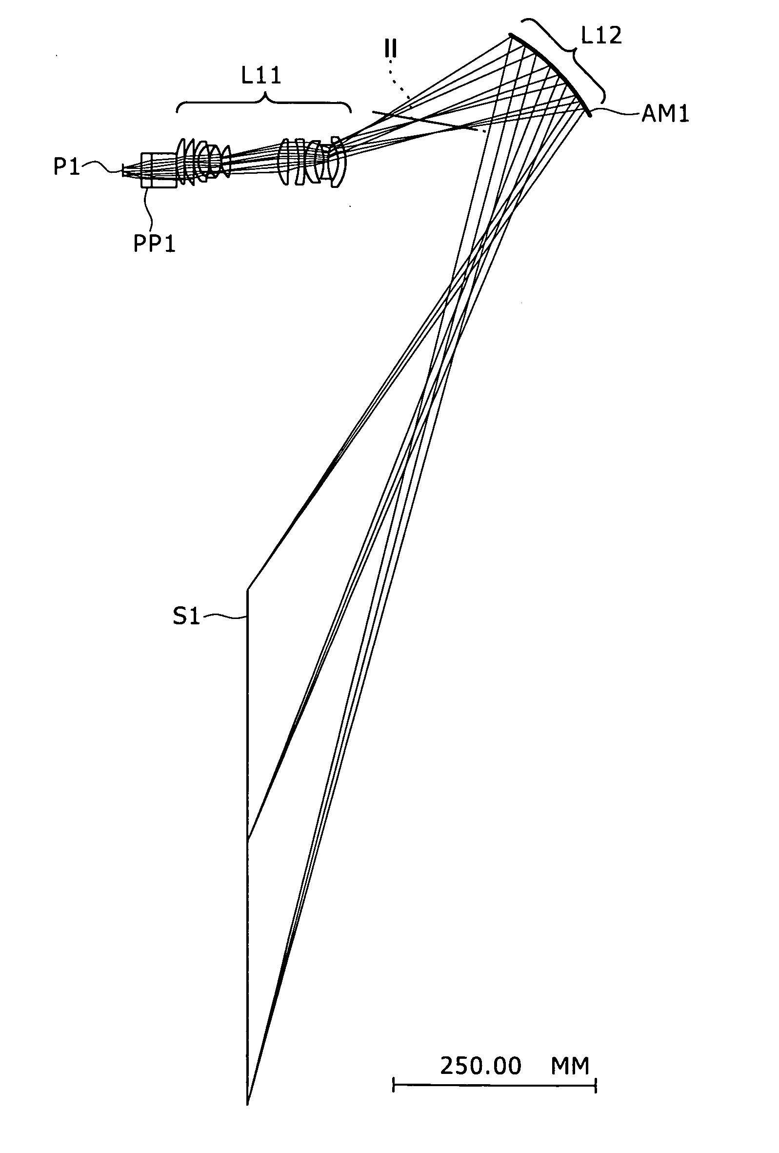
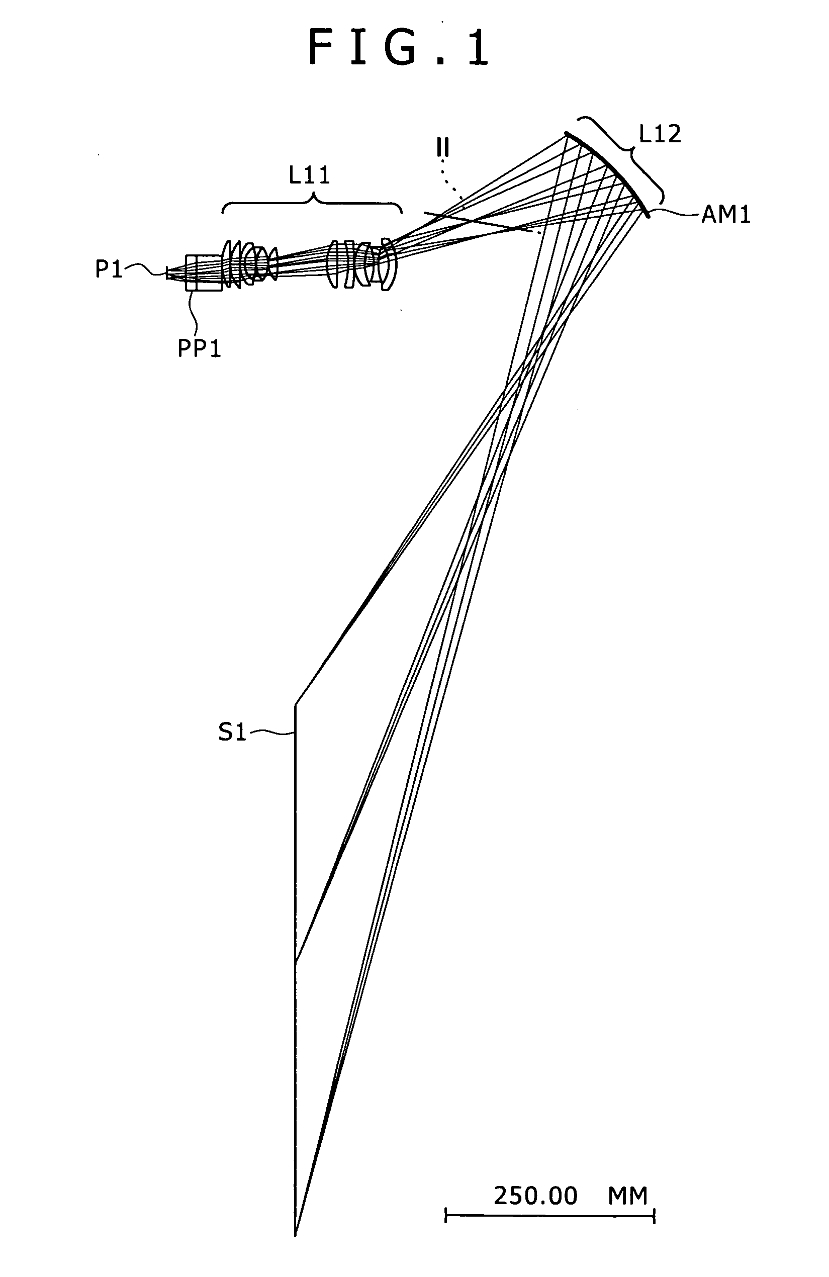
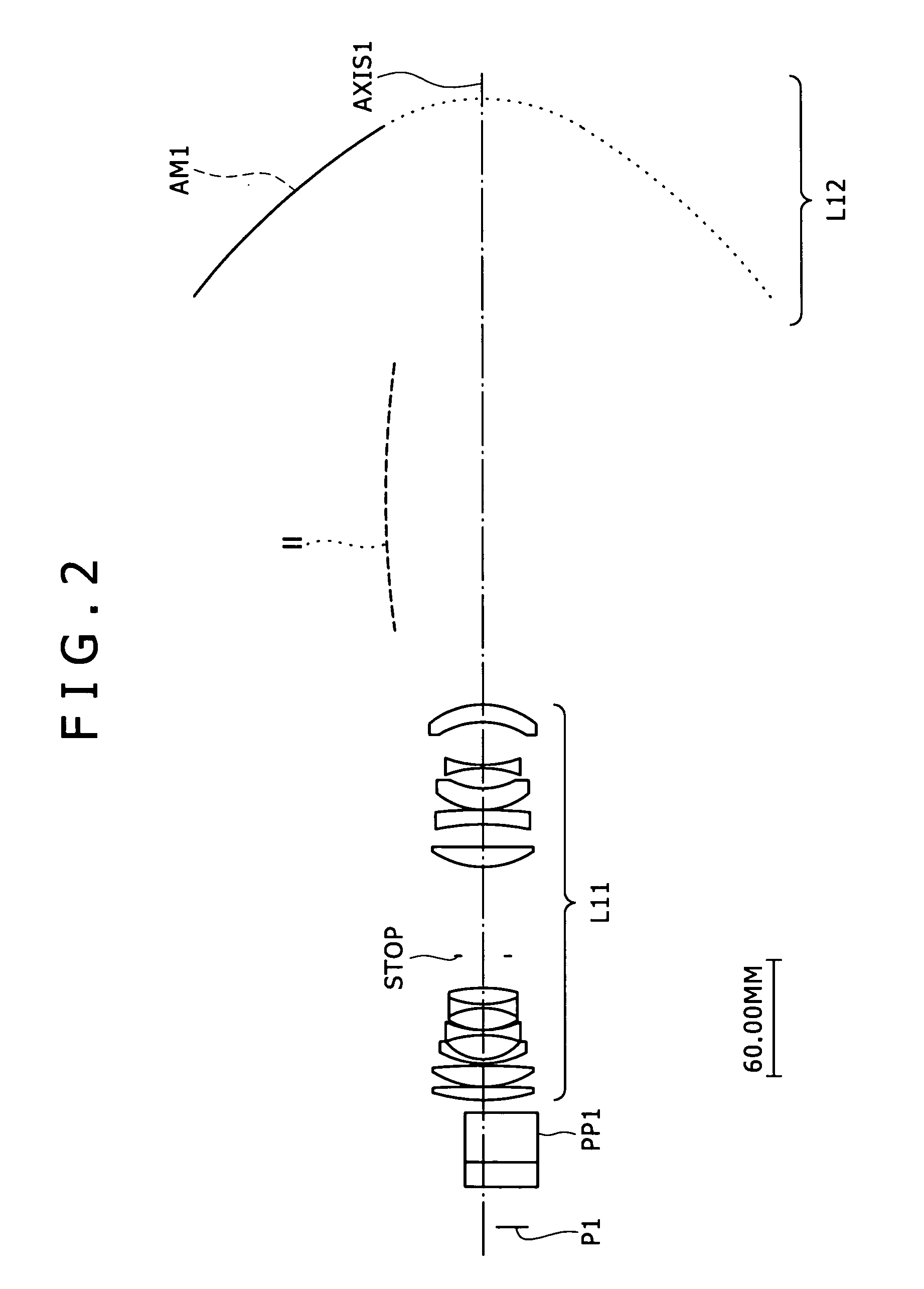
[0124]FIG. 1 outlines the entire optical system of a projector (projection-type image display apparatus) using the projection optical system according to a first embodiment of the invention. FIG. 2 shows an enlarged view of the projection optical system.

[0125] In the diagram illustrating the first embodiment, P1 denotes an image display element as the modulation means. Based on a video signal, the image display element P1 modulates the light emitted from a light source (not shown) to form the primary image surface. The image display element P1 can represent a reflective or transmissive dot-matrix liquid crystal panel, a digital micro mirror device (DMD), and the like. In the diagram, PP1 denotes a polarizing beam splitter (PBS), a 4P prism, a TIR (Total Internal Reflector) prism, and the like. STOP denotes a diaphragm. While the projector needs an illumination optical system to illuminate the image display element P1, the illumination optical system is omitted from FIGS. 1, 2, and ...

second embodiment

[0135]FIG. 10 outlines the entire optical system of a projector (projection-type image display apparatus) using the projection optical system according to a second embodiment of the invention. FIG. 11 shows an enlarged view of the projection optical system.

[0136] In the diagram illustrating the second embodiment, P2 denotes an image display element as the modulation means. Based on a video signal, the image display element P2 modulates the light emitted from a light source (not shown) to form the primary image surface. The image display element P2 can represent a reflective or transmissive dot-matrix liquid crystal panel, a digital micro mirror device (DMD), and the like. In the diagram, PP2 denotes a polarizing beam splitter (PBS), a 4P prism, a TIR (Total Internal Reflector) prism, and the like. STOP denotes a diaphragm. While the projector needs an illumination optical system to illuminate the image display element P2, the illumination optical system is omitted from FIGS. 10, 11...

third embodiment

[0149]FIG. 20 outlines the entire optical system of a projector (projection-type image display apparatus) using the projection optical system according to a third embodiment of the invention. FIG. 21 shows an enlarged view of the projection optical system.

[0150] In the diagram illustrating the third embodiment, P3 denotes an image display element as the modulation means. Based on a video signal, the image display element P2 modulates the light emitted from a light source (not shown) to form the primary image surface. The image display element P3 can represent a reflective or transmissive dot-matrix liquid crystal panel, a digital micro mirror device (DMD), and the like. In the diagram, PP3 denotes a polarizing beam splitter (PBS), a dichroic prism, a TIR (Total Internal Reflector) prism, and the like. STOP denotes a diaphragm. While the projector needs an illumination optical system to illuminate the image display element P3, the illumination optical system is omitted from FIGS. 20...


PUM

PropertyMeasurementUnit
sizesaaaaaaaaaa
pixel sizeaaaaaaaaaa

Abstract

There is a need for providing a projection optical system that is appropriate for maintaining high resolution with low distortion, miniaturizing a reflector, decreasing the number of reflectors, and decreasing the depth and the bottom (or top) of a display used for a rear projection television, for example. The projection optical system according to the invention enlarges and projects images from a primary image surface existing at a reducing side to a secondary image surface existing at an enlarging side. The projection optical system has a first optical system L11 and a second optical system L12. The first optical system L11 forms an intermediate image (position II) of the primary image surface. The second optical system L12 has a concave reflector AM1 that forms the secondary image surface resulting from the intermediate image. A light beam travels from the center of the primary image surface and to the center of the secondary image surface and crosses an optical axis. The light beam is reflected on the concave reflector, crosses the optical axis again, and reaches the secondary image surface.

Description

TECHNICAL FIELD [0001] The present invention relates to a new projection optical system and a new projection-type image display apparatus. More specifically, the invention relates to a technology that maintains high resolution with low distortion, provides a small depth, and decreases the bottom (or top) of a screen. BACKGROUND ART [0002] Recently, there is an increasing demand for rear projection televisions. The rear projection television has the feature of flat television represented by LCD (Liquid Crystal Display) direct-view television and PDP (Plasma Display Panel). Compared to these televisions, the rear projection television provides a system that enlarges and projects an image display element as large as approximately one inch. Consequently, the rear projection television is available at low costs. The rear projection television is relatively easily compliant with demands for high image quality of full HD (high definition) signal levels represented by BS (Broadcasting Satel...

Claims


Application Information

Patent Timeline
Patent Type & Authority Applications(United States)
IPC IPC(8): G03C5/00
CPCG02B17/08G02B17/0816G03B21/28G03B21/10G02B17/0852
Inventor NISHIKAWA, JUNSUNAGA, TOSHIHIRO
Owner SONY CORP
Why Eureka
Try Eureka