Hydrocarbon Recovery from Subterranean Formations

a technology of subterranean formations and hydrocarbon recovery, which is applied in the direction of fluid removal, insulation, borehole/well accessories, etc., to achieve the effect of maximizing the growth of the steam zone and low viscosity

Inactive Publication Date: 2007-08-16
CRICHLOW HENRY B
View PDF3 Cites 23 Cited by
  • Summary
  • Abstract
  • Description
  • Claims
  • Application Information

AI Technical Summary

Benefits of technology

The patent aims to achieve three specific objectives: replacing oil with steam, pressure up the steam bank to displace oil downwards, and using accumulated oil as a hydraulic seal to maximize the growth of the steam zone in the reservoir. Additionally, the produced oil acts as a backpressure system to prevent steam from breaking through the wellbore.

Problems solved by technology

The technical problem addressed in this patent is how to recover hydrocarbons more efficiently from deep oil deposits containing bitumen and other substances like sand and water.

Method used


Image

  • Hydrocarbon Recovery from Subterranean Formations
  • Hydrocarbon Recovery from Subterranean Formations
  • Hydrocarbon Recovery from Subterranean Formations

Examples


Embodiment Construction

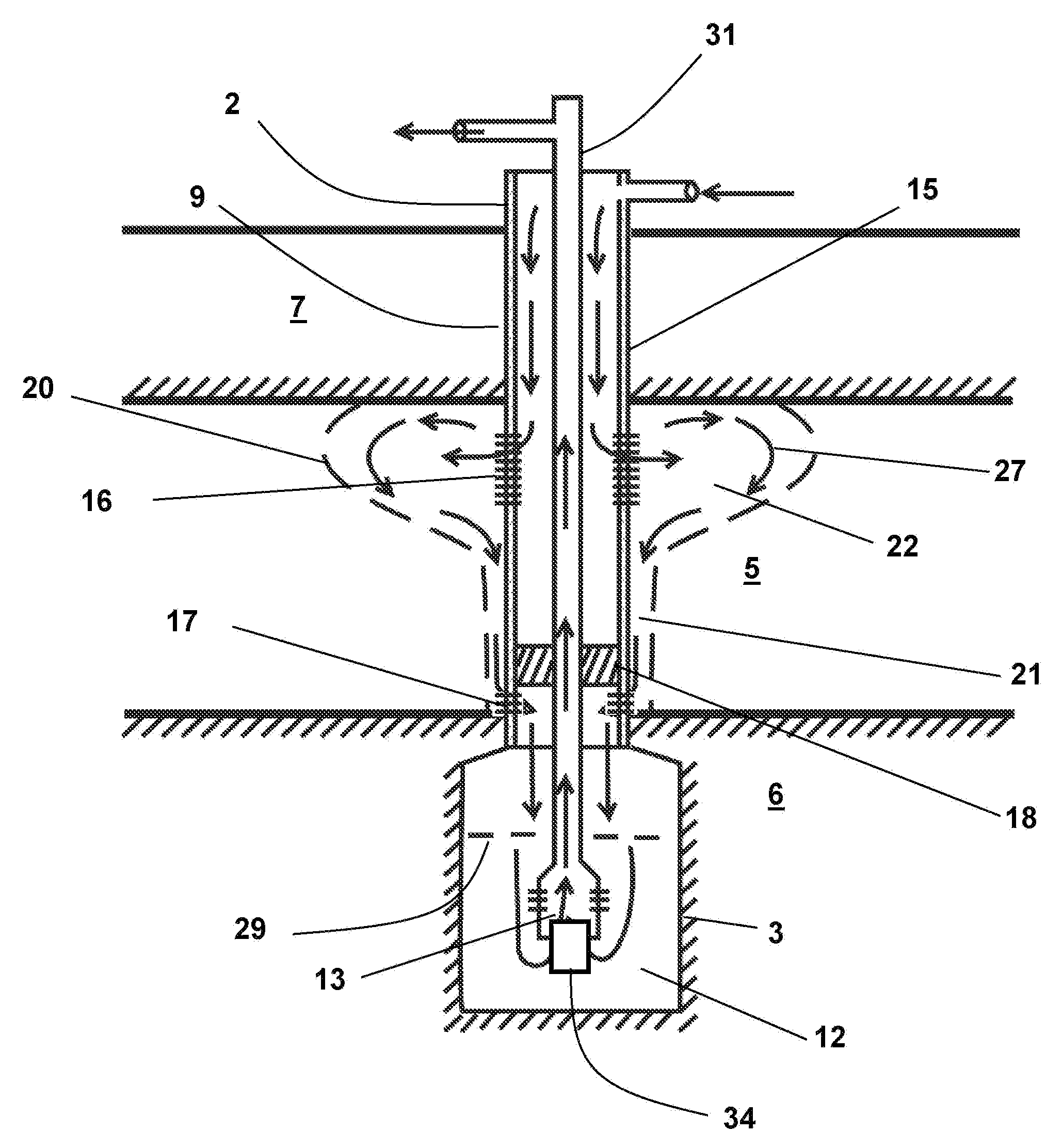
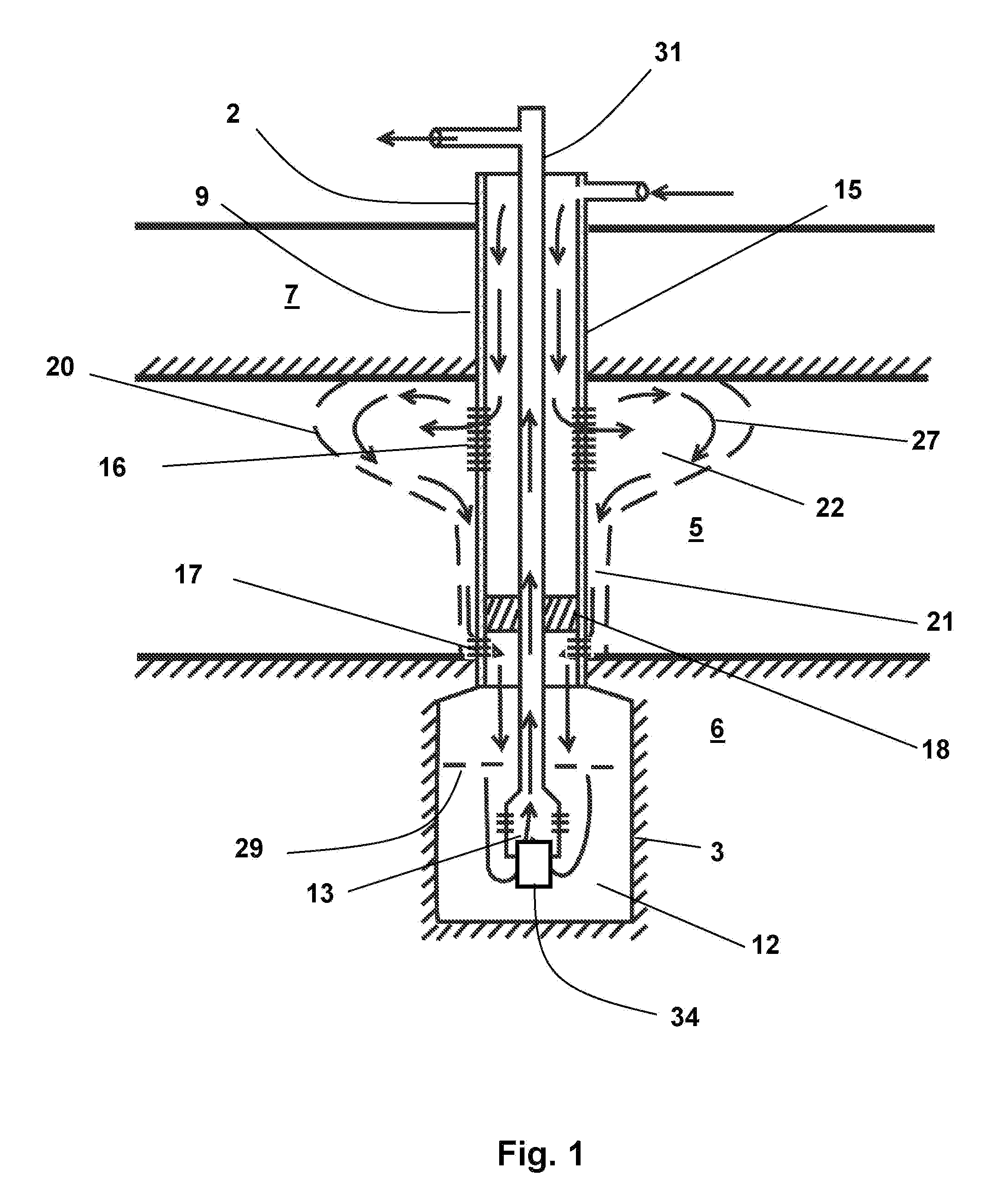
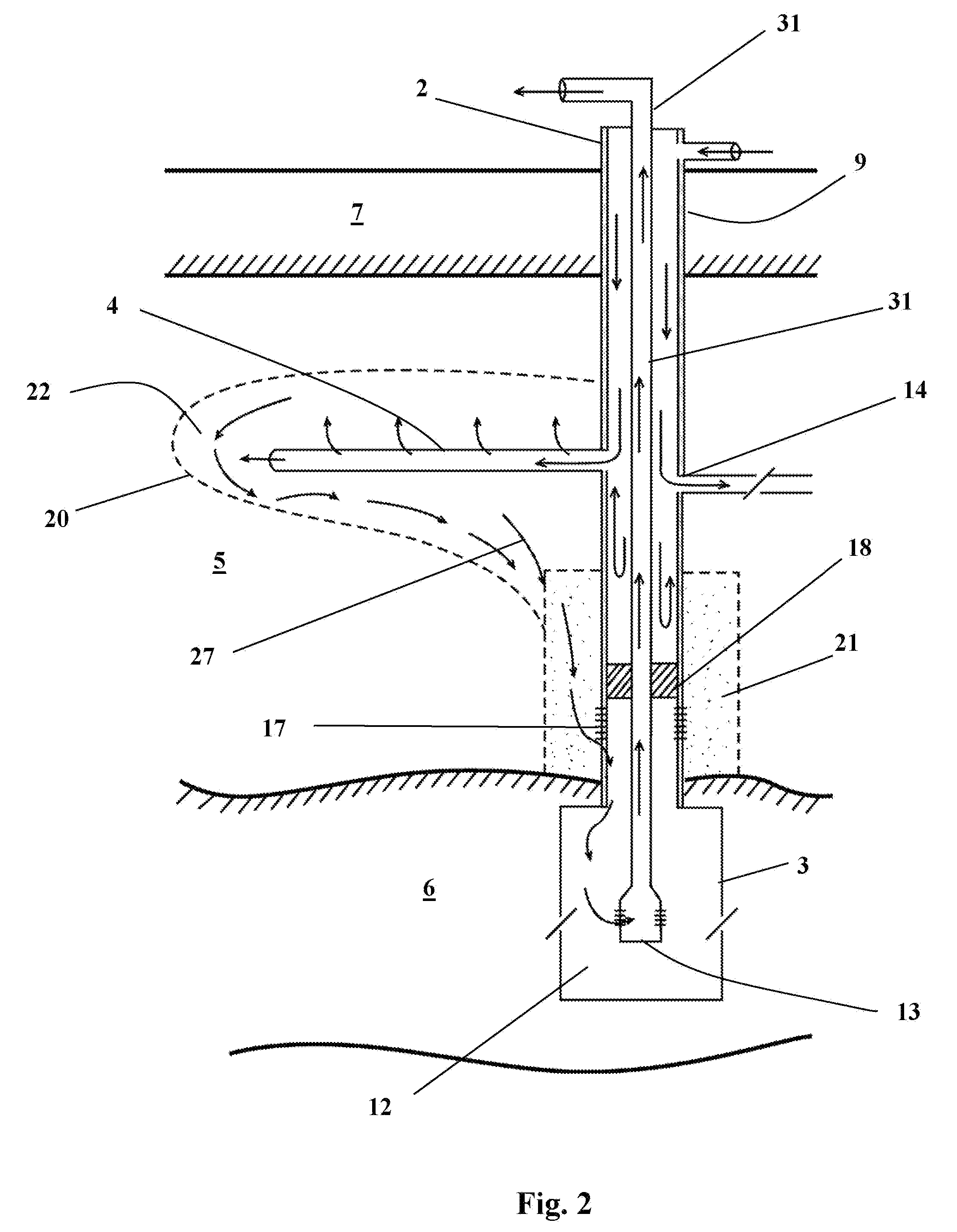
[0132] Referring now to the drawings the new method is described as follows. Referring to FIG. 1 and FIG. 10, a central wellbore 2 is drilled from the surface of the ground 1 down to and passing through the hydrocarbon bearing formation 5 as shown in step 100. The central wellbore is under-reamed by using a reamer tool to provide a large cavity 3 up to as much as 8 feet in diameter and several feet deep as indicated in step 101. This cavity 3 can be implemented in the oil formation 5 or ideally in the under-burden formation 6 or in a both zones at the same time. Standard oilfield tools as provided by Ref. 2 are capable of performing this operation routinely. After the central well 2 is drilled and under-reamed to form a production cavity 3 as shown in step 101, the central wellbore 2 is completed and cemented in the formation 5 with steel casing 15 and perforations 16 and 17 made at pre-selected intervals is the wellbore as indicated in step 102. In other embodiments an “open-hole” ...


PUM


Abstract

Recovery of viscous hydrocarbon by hot fluid injection into subterranean formations is assisted by using a specially designed and under-reamed vertical wellbore with multiple injection perforations separated from the production perforations by a moveable packer. In this oil recovery method the operator drills a typical vertical well, in which a cavity is developed below the pay zone by under-reaming the vertical wellbore to form a collection cavity. This under-reaming can be made up to several feet in diameter using standard reaming technology and tools. Steam is injected into the upper perforations and is prevented from bypassing the cold formation by a vertical hydraulic seal developed in an annular communication zone. Hot oil is produced into the lower perforations and is collected in the reamed out production cavity. A producing mechanism including pumping equipment lifts the produced oil from the central cavity to the surface.

Description


Claims


Application Information

Patent Timeline
Owner CRICHLOW HENRY B
Why Eureka
Try Eureka